
Das Projekt Nein Fo-Fo
-
troyguitar

- Command Chief Master Sirloin

- Posts: 20088
- Joined: Wed Nov 02, 2016 11:15 pm
- Drives: Trek Domane
- Location: Swamp
I have used ebay spring compressors on ebay springs NFG.
-
ChrisoftheNorth

- Moderator

- Posts: 47112
- Joined: Thu Nov 03, 2016 6:10 am
- Drives: 4R
I have ones I bought at HF and have used a number of times fine. But I make sure the threads are well lubricated and tighten both sides equally when using.troyguitar wrote: ↑Mon Nov 02, 2020 2:53 pm I have used ebay spring compressors on ebay springs NFG.
But notice how on that meme, there's' only one compressor. I'd never do that personally.
Desertbreh wrote: ↑Tue Oct 10, 2017 6:40 pm My guess would be that Chris took some time off because he has read the dialogue on this page 1,345 times and decided to spend some of his free time doing something besides beating a horse to death.
-
troyguitar
- Command Chief Master Sirloin
- Posts: 20088
- Joined: Wed Nov 02, 2016 11:15 pm
- Drives: Trek Domane
- Location: Swamp

Those wood clamps also won't do shit vs a car spring. Memes are


-
ChrisoftheNorth
- Moderator
- Posts: 47112
- Joined: Thu Nov 03, 2016 6:10 am
- Drives: 4R
Exactly what makes it so terrifying to me.troyguitar wrote: ↑Mon Nov 02, 2020 3:01 pm
Those wood clamps also won't do shit vs a car spring. Memes are
Definitely a Russian Trollfarm operative infiltrating the car enthusiast market with that meme here.
Desertbreh wrote: ↑Tue Oct 10, 2017 6:40 pm My guess would be that Chris took some time off because he has read the dialogue on this page 1,345 times and decided to spend some of his free time doing something besides beating a horse to death.
-
Huckleberry

- Senior Chief Patty Officer

- Posts: 2426
- Joined: Tue Nov 20, 2018 9:10 am
- Drives: 2004 GTO
- Location: Hi. I'm in Delaware.
Melon wrote: ↑Mon Nov 02, 2020 1:44 pmChild's play for men like us.Huckleberry wrote: ↑Mon Nov 02, 2020 12:34 pm
Well, the inserts are available. So, I would need to disassemble the strut body and replace the insert.


-
Huckleberry
- Senior Chief Patty Officer
- Posts: 2426
- Joined: Tue Nov 20, 2018 9:10 am
- Drives: 2004 GTO
- Location: Hi. I'm in Delaware.
Yeah, stored energy in a compressed spring is no joke. For a strut spring, you need both compressors on, or else you're playing with sweating dynamite.Detroit wrote: ↑Mon Nov 02, 2020 2:58 pmI have ones I bought at HF and have used a number of times fine. But I make sure the threads are well lubricated and tighten both sides equally when using.troyguitar wrote: ↑Mon Nov 02, 2020 2:53 pm I have used ebay spring compressors on ebay springs NFG.
But notice how on that meme, there's' only one compressor. I'd never do that personally.
-
Huckleberry
- Senior Chief Patty Officer
- Posts: 2426
- Joined: Tue Nov 20, 2018 9:10 am
- Drives: 2004 GTO
- Location: Hi. I'm in Delaware.
It's been a slow-going process with the motor. Needless to say, I still don't have it back yet. The machine shop called and said that they calculated the spring pressure at the specified 1.800" height to be around 200lbs, which is about 15lbs more than the max seat pressure that is specified for the Isky lifters I had purchased. Initially, when Howards gave me the spring part number and I saw that the seat pressure was rated at a 1.940" install height, I asked what the spring pressure would be at 1.800". The reply I received was 165-170lbs, which prompted me to buy the Isky lifters. Would the lifters be fine with 200lbs of seat pressure? Possibly, but if I have a failure, then Isky would certainly tell me to pound sand due to running too much seat pressure. So, I reached out to Howards to get a parts exchange, since they gave me bad information and I had the emails to back up their giving me bad information. They told me to pound sand and just return the parts to the vendor. So, all of those nice things I said about Howards earlier? Fuck 'em. That is the first and last time I will ever do business with them.
The machine shop said that they had a spring in mind as a replacement. I told them to give me the part number so I can try and do an exchange with the vendor. It was crickets after that. I asked a few more times, was told they would get back with me, and then more crickets. So, I started looking around for a new spring myself. At the same time, since I had sourced the parts through two different vendors on eBay, I reached out to them to see about exchanges. Autoplicity can also fuck right off, as they told me tough shit since I had bought the stuff more than 30 days ago. Performance Parts Racing, however, was very understanding and willing to work with me. They simply asked for pictures of the items as proof that they were still new and uninstalled. They even went so far as to source the new parts I needed since they were not an item that they kept in stock.
After looking at springs for a while, I settled on Isky 8005SP. I calculated the 1.800" pressure to be 181lbs and the open pressure to be 416lbs at .565" of lift. This also puts the spring within .070" of coil bind. I originally was going to use the Howards retainers and locks I had purchased, but decided to just go with all of Isky's stuff in case things didn't jive. Mostly, the diameter of the step was too different between the two retainers. The Howards retainer is at 1.005", while Isky's is at 1.015". It is another unfortunate incurred expense, but hopefully it is now corrected. Buy once, cry once...unless the manufacturer lies to you with bad information and then tells you to get fucked when you point out their mistake.
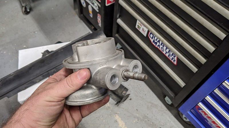
While I am waiting for the Isky parts to arrive, I have taken care of as much as I can without the motor in place. I'm going to be using an oil cooler, and cleaned up the factory oil cooler adapter for the engine. I cut off the flex lines and installed some 1/2" to -8AN compression fittings:
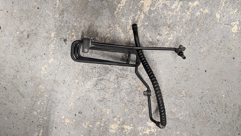
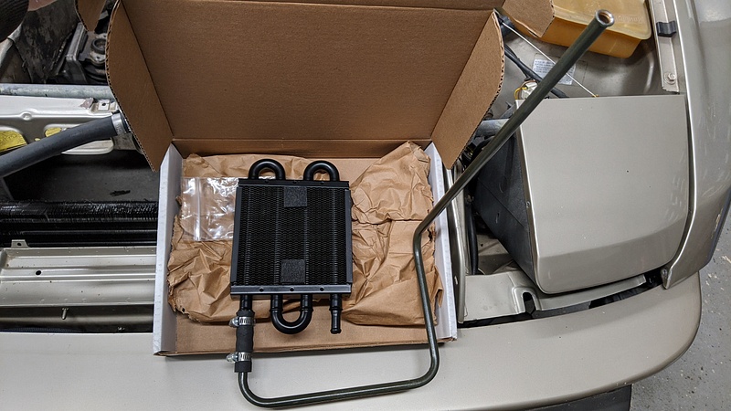
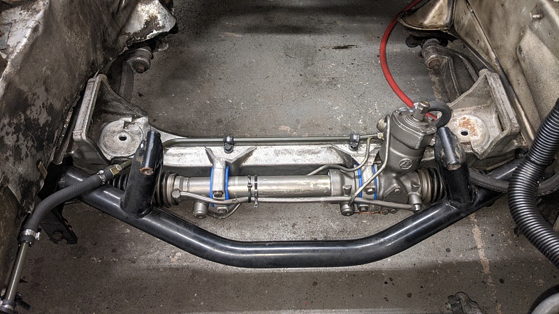
I pulled out the factory power steering cooler:
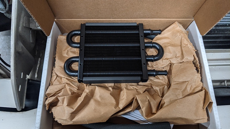
And replaced it with something that can be mounted in front of the condenser:
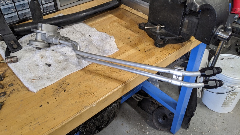
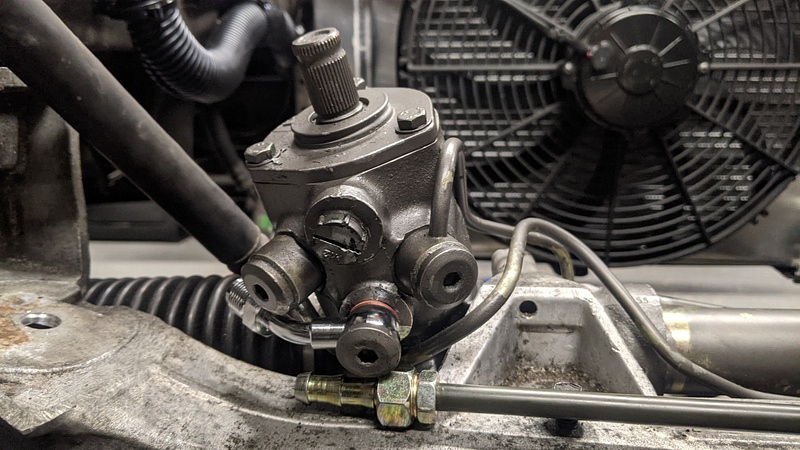
I got some 3/8" brake line and bent it into shape for routing to the steering rack:
The steering rack had used M12 banjo fittings originally. So, I found an M12 to -6AN steel fitting for the pressure port and an M12 to 3/8" barb fitting for the return port:
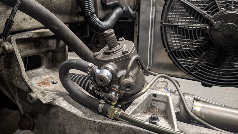
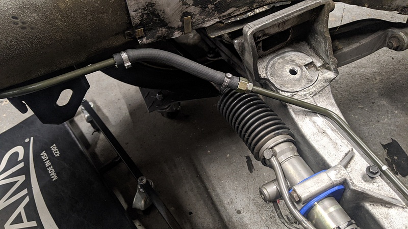
And then used a flex line to bridge between the body and the crossmember, keeping a disconnection point for when the crossmember needs to come out:
I also tidied up the wiring on the driver's side since the engine harness won't be passing through there. Porsche uses threaded studs welded to the body as mounting points for the wiring harness, instead of the usual drilled holes and wire clips. Basically, they secure the loom with a ziptie strap that screws onto the stud. Luckily, Panduit makes a part that works: PLST30SC-D30:

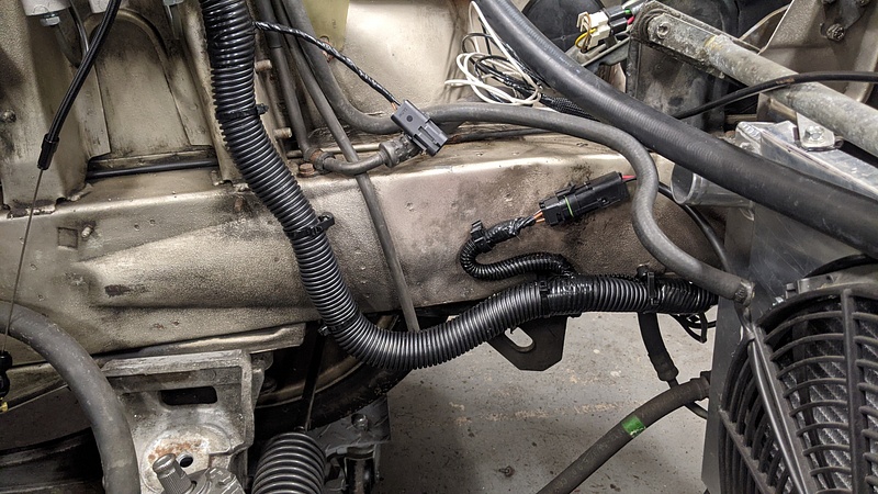
As you can see, the Spal fan is wired into the factory harness. I will be utilizing the stock relay and connecting the original trigger wires to the Holley for fan control.
The last thing I have done is compress the springs on the struts so I can test their functionality. The struts' ease of compression changes with the valving, so they appear to still be okay. Luckily, they are just Koni inserts, so I can simply order new ones down the line when the time comes. My plan is to install them once the motor is ready to go in since the suspension will have to come apart anyways.
I wish I had more to update, but it has been a rather infuriating process dealing with some of these vendors.
The machine shop said that they had a spring in mind as a replacement. I told them to give me the part number so I can try and do an exchange with the vendor. It was crickets after that. I asked a few more times, was told they would get back with me, and then more crickets. So, I started looking around for a new spring myself. At the same time, since I had sourced the parts through two different vendors on eBay, I reached out to them to see about exchanges. Autoplicity can also fuck right off, as they told me tough shit since I had bought the stuff more than 30 days ago. Performance Parts Racing, however, was very understanding and willing to work with me. They simply asked for pictures of the items as proof that they were still new and uninstalled. They even went so far as to source the new parts I needed since they were not an item that they kept in stock.
After looking at springs for a while, I settled on Isky 8005SP. I calculated the 1.800" pressure to be 181lbs and the open pressure to be 416lbs at .565" of lift. This also puts the spring within .070" of coil bind. I originally was going to use the Howards retainers and locks I had purchased, but decided to just go with all of Isky's stuff in case things didn't jive. Mostly, the diameter of the step was too different between the two retainers. The Howards retainer is at 1.005", while Isky's is at 1.015". It is another unfortunate incurred expense, but hopefully it is now corrected. Buy once, cry once...unless the manufacturer lies to you with bad information and then tells you to get fucked when you point out their mistake.
While I am waiting for the Isky parts to arrive, I have taken care of as much as I can without the motor in place. I'm going to be using an oil cooler, and cleaned up the factory oil cooler adapter for the engine. I cut off the flex lines and installed some 1/2" to -8AN compression fittings:
I pulled out the factory power steering cooler:
And replaced it with something that can be mounted in front of the condenser:
I got some 3/8" brake line and bent it into shape for routing to the steering rack:
The steering rack had used M12 banjo fittings originally. So, I found an M12 to -6AN steel fitting for the pressure port and an M12 to 3/8" barb fitting for the return port:
And then used a flex line to bridge between the body and the crossmember, keeping a disconnection point for when the crossmember needs to come out:
I also tidied up the wiring on the driver's side since the engine harness won't be passing through there. Porsche uses threaded studs welded to the body as mounting points for the wiring harness, instead of the usual drilled holes and wire clips. Basically, they secure the loom with a ziptie strap that screws onto the stud. Luckily, Panduit makes a part that works: PLST30SC-D30:
As you can see, the Spal fan is wired into the factory harness. I will be utilizing the stock relay and connecting the original trigger wires to the Holley for fan control.
The last thing I have done is compress the springs on the struts so I can test their functionality. The struts' ease of compression changes with the valving, so they appear to still be okay. Luckily, they are just Koni inserts, so I can simply order new ones down the line when the time comes. My plan is to install them once the motor is ready to go in since the suspension will have to come apart anyways.
I wish I had more to update, but it has been a rather infuriating process dealing with some of these vendors.


-
Huckleberry
- Senior Chief Patty Officer
- Posts: 2426
- Joined: Tue Nov 20, 2018 9:10 am
- Drives: 2004 GTO
- Location: Hi. I'm in Delaware.
It has been a while since an update, but here we go.
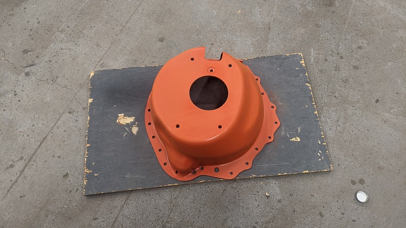
A while back, I found a Lakewood blowproof bellhousing on Craigslist for a song. Since I do intend on taking this car out to some track days, I figured it would be some insurance for my feet incase something decides to go horribly wrong. The bellhousing was already painted Chevy orange, so I gave it a quick scuff and color change:
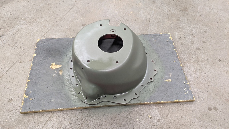
Self-etching primer:
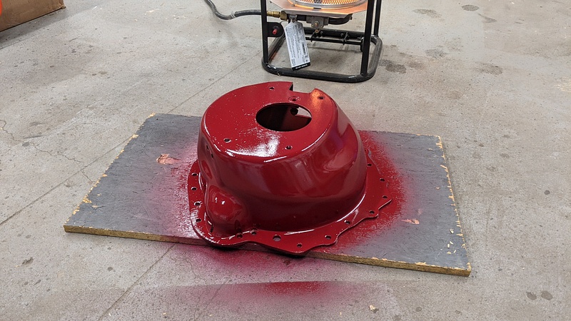
Final color:
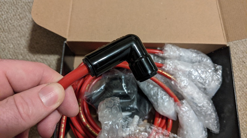
I picked up some Taylor 8.2mm plug wires that are for LS ignition coil relocations. Since I'm not sure exactly where or how the ignition coils are going to be mounted, I can cut these wires to length.
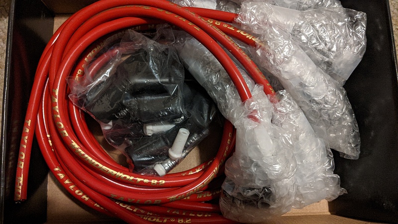
They have 90° ceramic boots to help with the heat from the headers:
I picked up some power steering fittings and hose from Earl's to make up the pressure lines for the steering rack and the hydroboost. I have used this system from Earl's before on the El Camino and Impala without issue. It is a great design that doesn't use compression sleeves and only requires some wrenches and a vise.
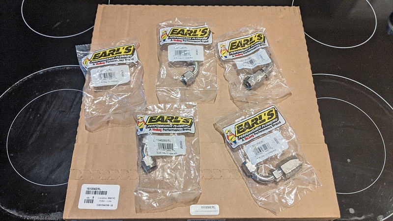
The fittings install in minutes and you can clock the end up to one full turn:
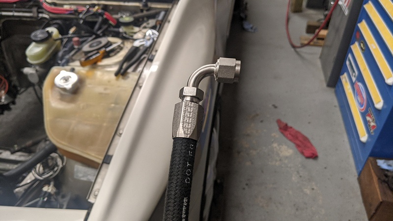
I made up and installed the line going from the the hydroboost to the steering rack. As you may be able to tell from the wire loom and brake master lines, I'm aiming to keep as much clearance from the exhaust as possible by tucking everything against the strut towers:
Now, for the big announcement: I finally got the motor back!
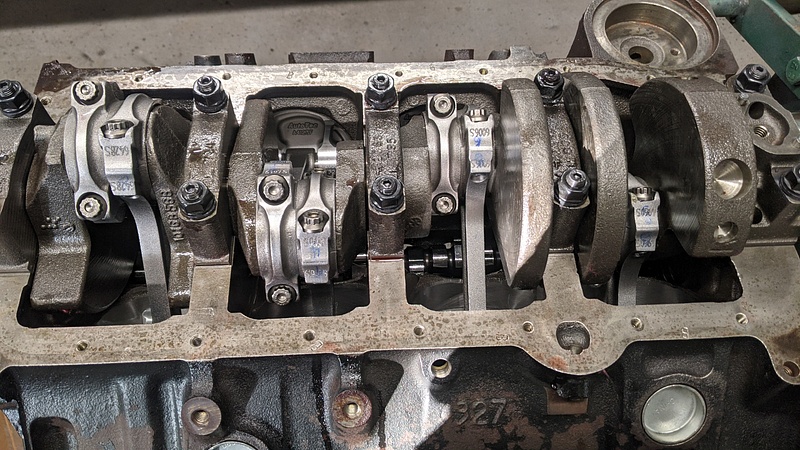
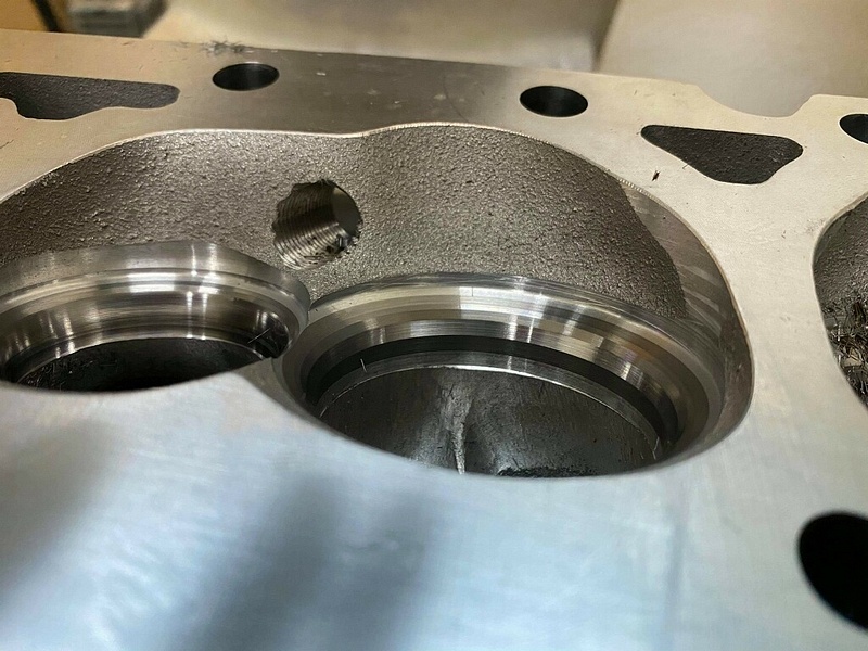
One thing that is unique to the LT1 is that there is a ball that gets wedged under the rear main cap to divert oil to the filter. Not many people know about it, but it is an important piece of the motor. You can see it in the hole next to the stud:
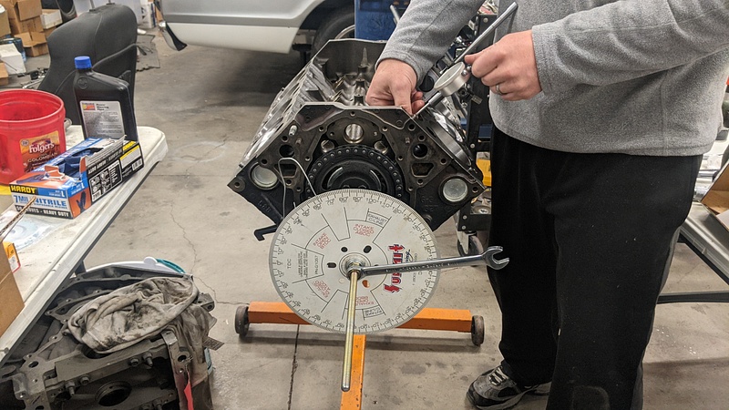
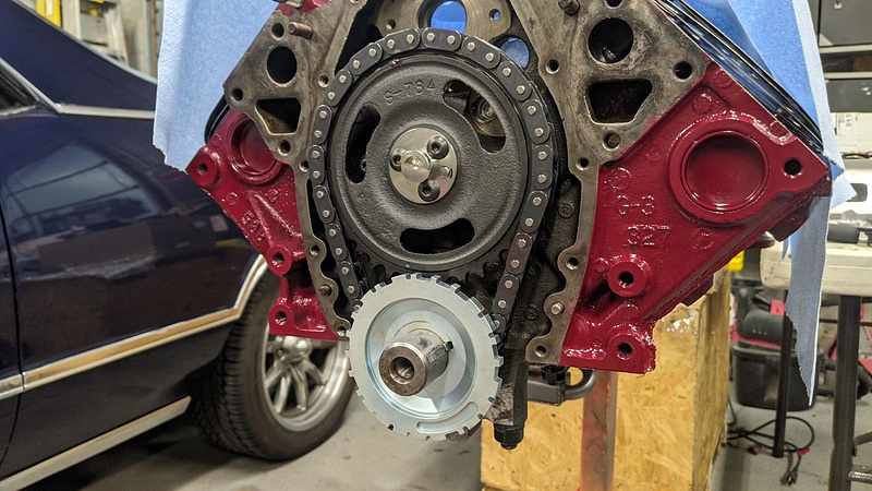
I degreed the cam to see if it was within spec. It wound up being 1° off from the card. The Cloyes timing set I got was able to be advanced or retarded by 4°, and the offset bushings come in steps of 2°, so the cam will be installed straight up.
Melling has a new oil pump gear design that they call "shark tooth." It is supposed to help against cavitation at higher RPMs. These pumps are designated with an "ST" at the end of the part number. So, I picked one up and installed it along with the pickup tube for the oil pan from Kevko:
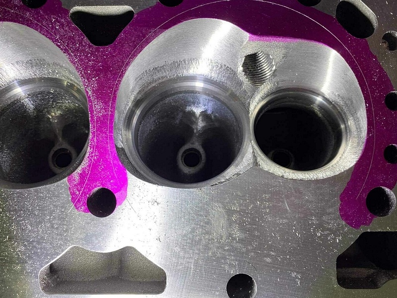
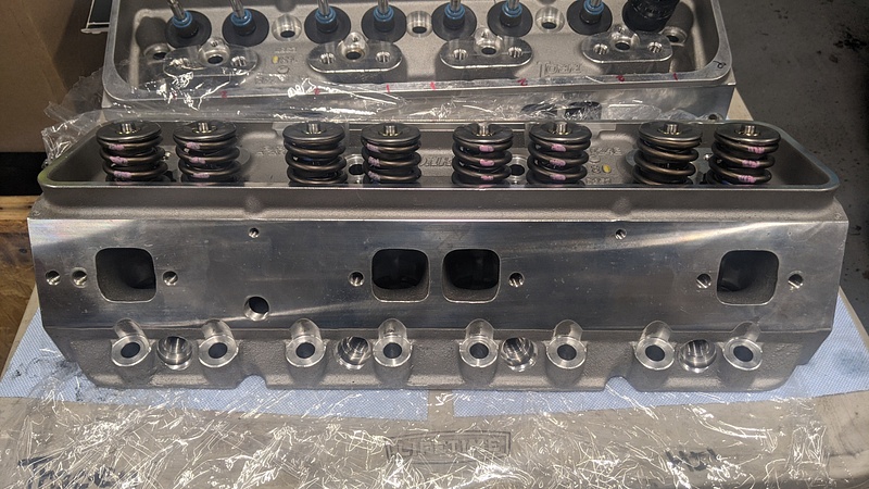
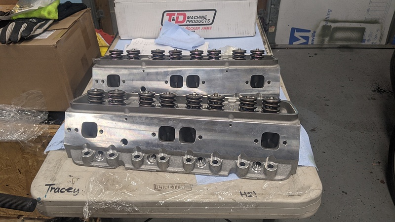
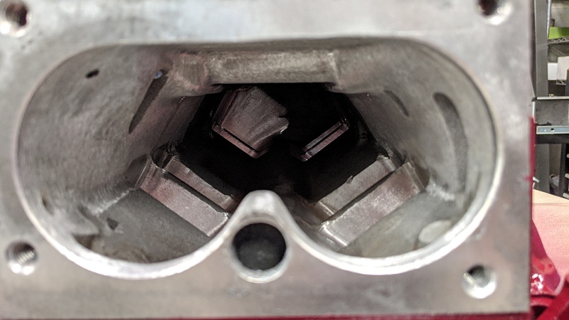
While the Dart heads were at the machine shop, I had some chamber work done since the chambers didn't look all that great as-is from Dart:
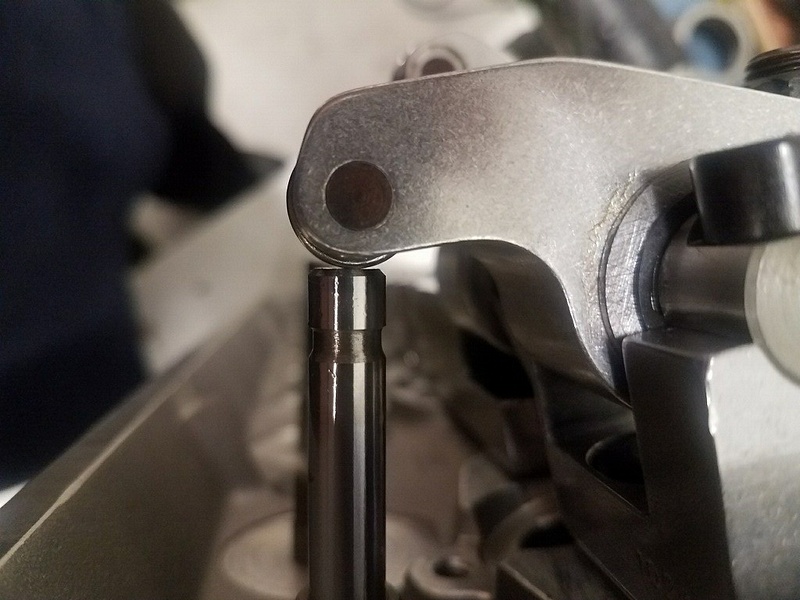
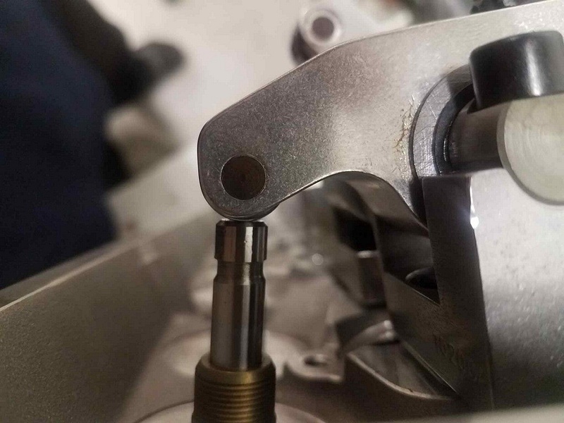
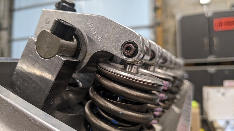
Shimming and checking the T&D rockers for proper valve contact:
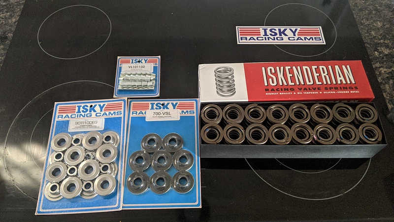
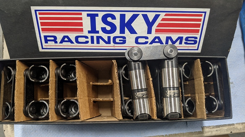
The new valvetrain from Isky. When comparing this stuff to what I had originally gotten from Howards, the difference is night and day:
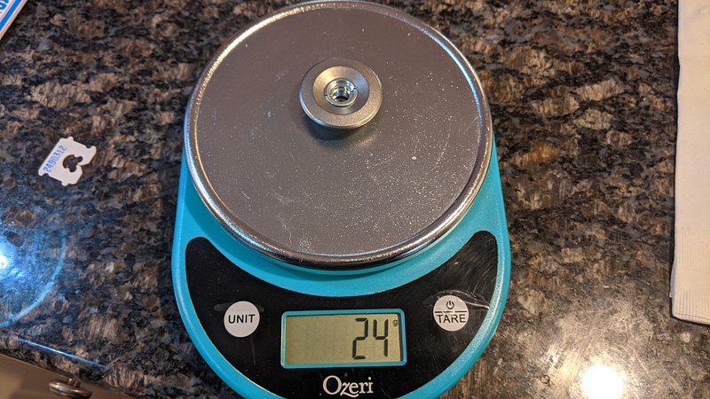
The weight of the Isky titanium retainer and 10° locks:
Unfortunately, while measuring the spring height, it turned out that I needed to get some -.050 locks to get close to 1.800". I placed a call to Isky, because as great as their parts are, their website is atrocious and I couldn't find any -.050" locks. To my surprise, they don't carry any + or - locks. So, I looked on Summit and ordered some -.050" locks from Crower, along with some spring shims from Comp. The Crower locks are on the left and Isky is on the right. You can see the difference in the tang heights:
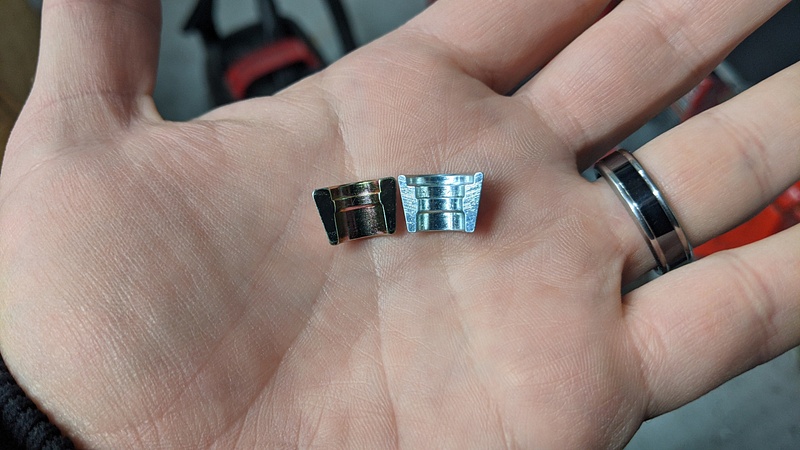
Now, this is why you always measure and never assume: the intake valves were originally measuring to 1.910" and the exhaust valves at 1.880". So, .060" shims and -.050" locks on the intake and .030" shims and -.050" locks on the exhaust would theoretically bring both valves to 1.800". Had I just bought the new locks and slapped them in, I would have been none the wiser. Upon measuring, the locks from Crower were turning out to be -.075" with the Isky retainers. So, what I wound up doing was using a .030" shim on the intake and no shim on the exhaust, and with some playing with the retainer/lock combinations, I was about to get the heads in the 1.810"-1.815" range. One intake valve came out to 1.808" and a couple exhaust valves were at 1.818". Seated pressure is in the 178lb range and open pressure is in the 405lb range, and the springs will all roughly be within .085"-.090" of coil bind.
Basically, as I measured, I kept the matching retainer and locks with the corresponding valve. The installed valve seals had to be pulled off after seeing that the locks brought the spring height down another .025" so that shims could be changed:
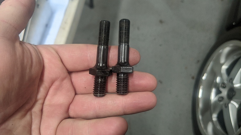
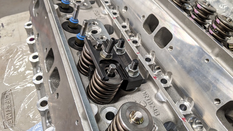
One fun discovery was the Dart heads were drilled for 7/16 bolts, and my spring tool from Crane could only use 3/8 studs. So, I had to order a pair of rocker studs from ARP that have a 7/16 base and a 3/8 stud so I could install the springs:
The tool from Crane is an awesome piece. I've had it for probably ten years now. However, I did need to grind the sides a little to get it to clear the 1.500" springs.
A while back, I found a Lakewood blowproof bellhousing on Craigslist for a song. Since I do intend on taking this car out to some track days, I figured it would be some insurance for my feet incase something decides to go horribly wrong. The bellhousing was already painted Chevy orange, so I gave it a quick scuff and color change:
Self-etching primer:
Final color:
I picked up some Taylor 8.2mm plug wires that are for LS ignition coil relocations. Since I'm not sure exactly where or how the ignition coils are going to be mounted, I can cut these wires to length.
They have 90° ceramic boots to help with the heat from the headers:
I picked up some power steering fittings and hose from Earl's to make up the pressure lines for the steering rack and the hydroboost. I have used this system from Earl's before on the El Camino and Impala without issue. It is a great design that doesn't use compression sleeves and only requires some wrenches and a vise.
The fittings install in minutes and you can clock the end up to one full turn:
I made up and installed the line going from the the hydroboost to the steering rack. As you may be able to tell from the wire loom and brake master lines, I'm aiming to keep as much clearance from the exhaust as possible by tucking everything against the strut towers:
Now, for the big announcement: I finally got the motor back!
One thing that is unique to the LT1 is that there is a ball that gets wedged under the rear main cap to divert oil to the filter. Not many people know about it, but it is an important piece of the motor. You can see it in the hole next to the stud:
I degreed the cam to see if it was within spec. It wound up being 1° off from the card. The Cloyes timing set I got was able to be advanced or retarded by 4°, and the offset bushings come in steps of 2°, so the cam will be installed straight up.
Melling has a new oil pump gear design that they call "shark tooth." It is supposed to help against cavitation at higher RPMs. These pumps are designated with an "ST" at the end of the part number. So, I picked one up and installed it along with the pickup tube for the oil pan from Kevko:
While the Dart heads were at the machine shop, I had some chamber work done since the chambers didn't look all that great as-is from Dart:
Shimming and checking the T&D rockers for proper valve contact:
The new valvetrain from Isky. When comparing this stuff to what I had originally gotten from Howards, the difference is night and day:
The weight of the Isky titanium retainer and 10° locks:
Unfortunately, while measuring the spring height, it turned out that I needed to get some -.050 locks to get close to 1.800". I placed a call to Isky, because as great as their parts are, their website is atrocious and I couldn't find any -.050" locks. To my surprise, they don't carry any + or - locks. So, I looked on Summit and ordered some -.050" locks from Crower, along with some spring shims from Comp. The Crower locks are on the left and Isky is on the right. You can see the difference in the tang heights:
Now, this is why you always measure and never assume: the intake valves were originally measuring to 1.910" and the exhaust valves at 1.880". So, .060" shims and -.050" locks on the intake and .030" shims and -.050" locks on the exhaust would theoretically bring both valves to 1.800". Had I just bought the new locks and slapped them in, I would have been none the wiser. Upon measuring, the locks from Crower were turning out to be -.075" with the Isky retainers. So, what I wound up doing was using a .030" shim on the intake and no shim on the exhaust, and with some playing with the retainer/lock combinations, I was about to get the heads in the 1.810"-1.815" range. One intake valve came out to 1.808" and a couple exhaust valves were at 1.818". Seated pressure is in the 178lb range and open pressure is in the 405lb range, and the springs will all roughly be within .085"-.090" of coil bind.
Basically, as I measured, I kept the matching retainer and locks with the corresponding valve. The installed valve seals had to be pulled off after seeing that the locks brought the spring height down another .025" so that shims could be changed:
One fun discovery was the Dart heads were drilled for 7/16 bolts, and my spring tool from Crane could only use 3/8 studs. So, I had to order a pair of rocker studs from ARP that have a 7/16 base and a 3/8 stud so I could install the springs:
The tool from Crane is an awesome piece. I've had it for probably ten years now. However, I did need to grind the sides a little to get it to clear the 1.500" springs.
-
Huckleberry
- Senior Chief Patty Officer
- Posts: 2426
- Joined: Tue Nov 20, 2018 9:10 am
- Drives: 2004 GTO
- Location: Hi. I'm in Delaware.
A while back, I sent the factory intake off to Lloyd Elliot for porting and opening up the mouth for a monoblade throttle body:
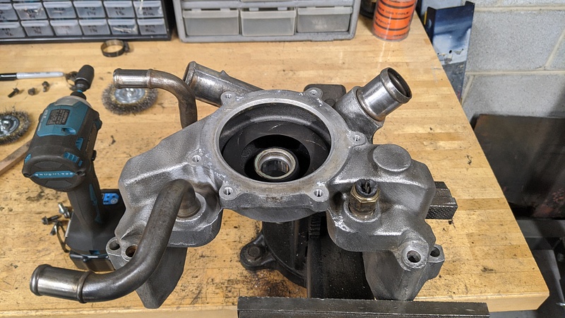
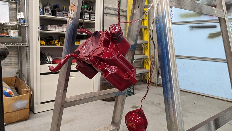
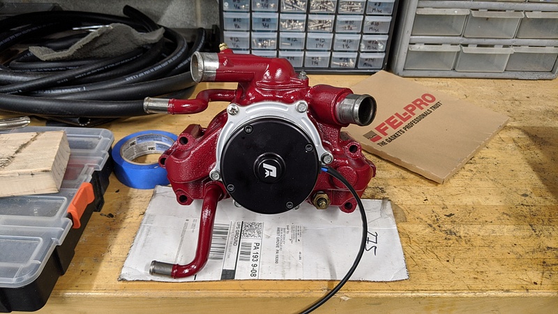
I also cleaned up, painted, and installed an electric water pump from Jegs:
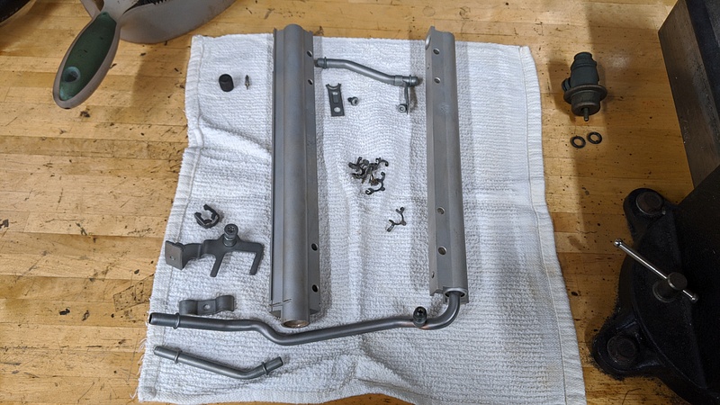
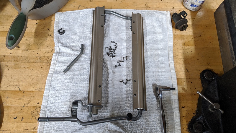
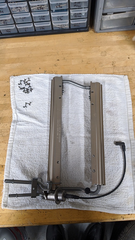
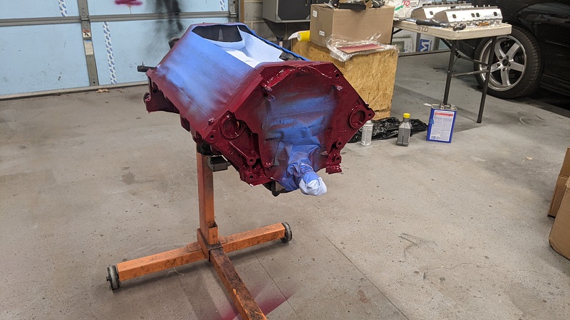
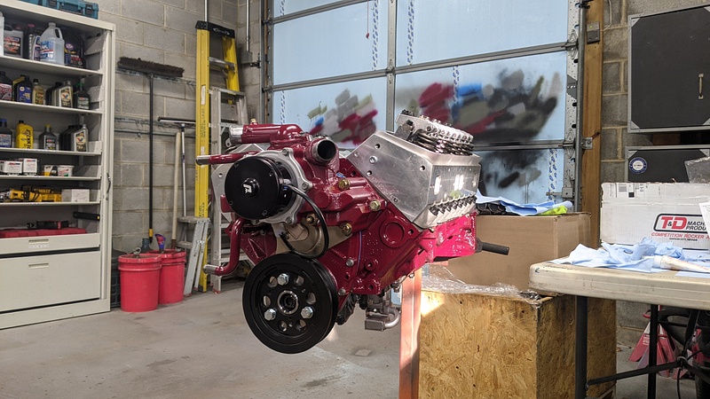
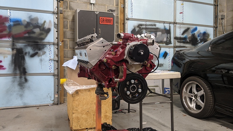
Since the car is gold with a burgundy interior, I decided the motor should be burgundy with some gold accents, so I cleaned up the stock fuel rails and shot them in gold:
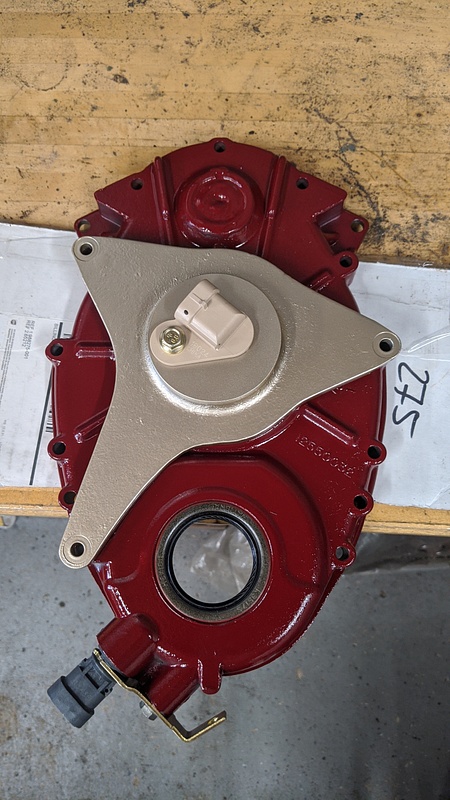
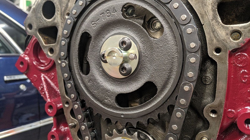
I did the same with the factory 96-97 timing cover, which has a crank sensor bung. EFI Connections makes a cam sensor bracket that bolts in place of the Optispark:
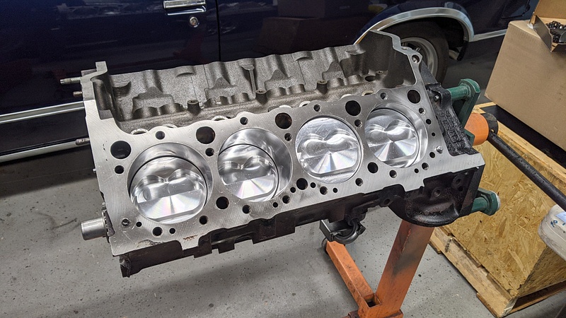
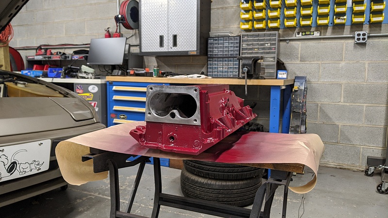
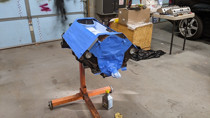
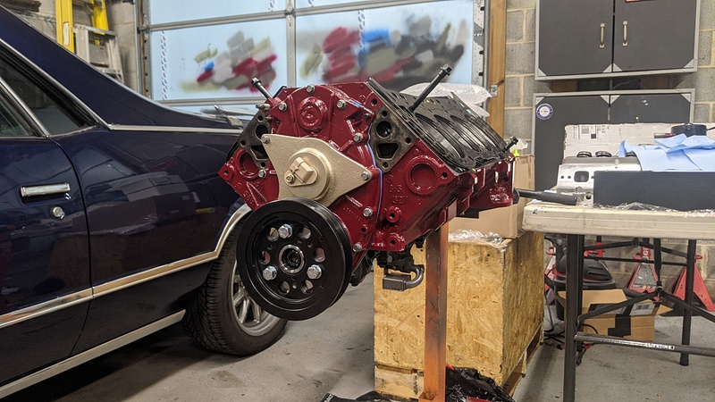
And of course, I prepped and painted the shortblock:
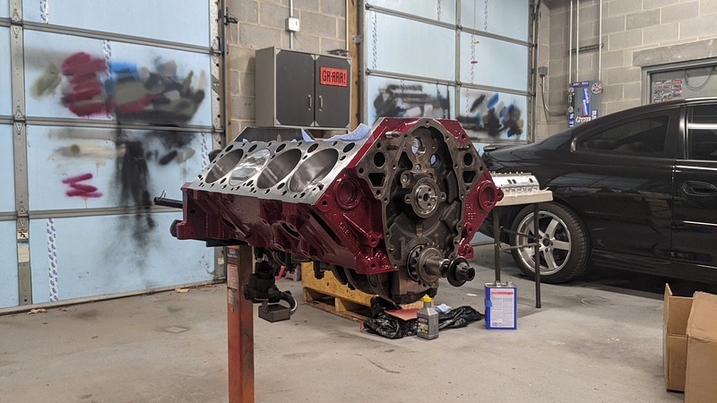
Next up will be installing the cylinder heads, lifters, rockers, and measuring for pushrods.
Oh, and pulling the motor off the stand so I can install the rear main cover and seal.

I also cleaned up, painted, and installed an electric water pump from Jegs:
Since the car is gold with a burgundy interior, I decided the motor should be burgundy with some gold accents, so I cleaned up the stock fuel rails and shot them in gold:
I did the same with the factory 96-97 timing cover, which has a crank sensor bung. EFI Connections makes a cam sensor bracket that bolts in place of the Optispark:
And of course, I prepped and painted the shortblock:
Next up will be installing the cylinder heads, lifters, rockers, and measuring for pushrods.
Oh, and pulling the motor off the stand so I can install the rear main cover and seal.
-
ChrisoftheNorth
- Moderator
- Posts: 47112
- Joined: Thu Nov 03, 2016 6:10 am
- Drives: 4R
Man I love these thread updates. Makes me want to pick up something eventually.
Desertbreh wrote: ↑Tue Oct 10, 2017 6:40 pm My guess would be that Chris took some time off because he has read the dialogue on this page 1,345 times and decided to spend some of his free time doing something besides beating a horse to death.


-
Huckleberry
- Senior Chief Patty Officer
- Posts: 2426
- Joined: Tue Nov 20, 2018 9:10 am
- Drives: 2004 GTO
- Location: Hi. I'm in Delaware.
Indeed. Now, if the carriers could stop delaying my parts, I can get underway and maybe get to a track this year.


-
ChrisoftheNorth
- Moderator
- Posts: 47112
- Joined: Thu Nov 03, 2016 6:10 am
- Drives: 4R

Desertbreh wrote: ↑Tue Oct 10, 2017 6:40 pm My guess would be that Chris took some time off because he has read the dialogue on this page 1,345 times and decided to spend some of his free time doing something besides beating a horse to death.
-
Huckleberry
- Senior Chief Patty Officer
- Posts: 2426
- Joined: Tue Nov 20, 2018 9:10 am
- Drives: 2004 GTO
- Location: Hi. I'm in Delaware.
The shipping delays and the holiday have been affecting everything, and this project is no exception.
After painting the block, I had to wait on a new cam retainer plate before I could continue installation. Once that arrived, I was able to proceed. In order to get the 1X cam signal for the Terminator X, I picked up a signal kit from EFI Connections, which bolts to the nose of the camshaft. Since the cam was made for an LT1, and LT1s have an extended cam dowel to drive the Optispakr, I had to knock it in to make sure that it would not get picked up by the cam sensor. I realized after the fact that it didn't need to go flush with the base, but the instructions read that the dowel "should not protrude higher than the lowest part." I took that as the entire piece instead of the lowest point of the signal. Oh well, it certainly isn't going to interfere now.
EFI Connections 24x crank wheel:
Timing cover with the EFI Connections cam sensor housing that bolts in place of the Opti, and the Jegs underdrive pulley and balancer:
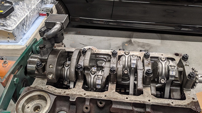
Once the cam was in, I dropped in the Isky short-travel lifters, made by Johnson. I also put the oil pump drive unit in just to get it off the work bench. I will have to remove it when it comes time to prime the motor with oil:
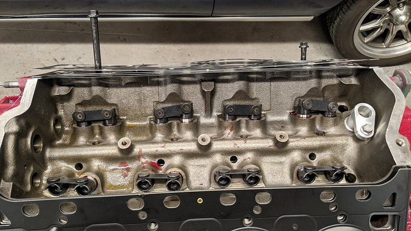
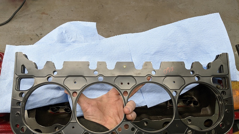
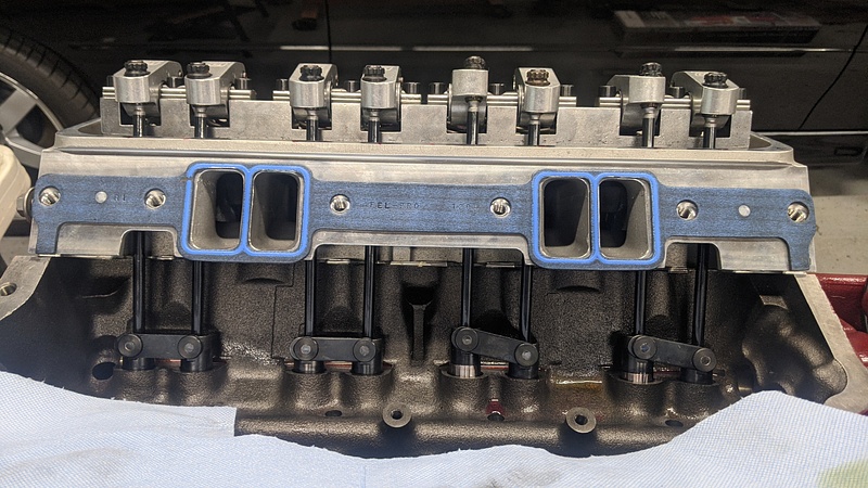
In the above picture, take notice of how the head gasket surrounds the pushrods. During mock-up for piston-valve clearance and such, I noticed that the 5/16" pushrods were rubbing in those areas. Since I was planning on using 11/32" or 3/8" pushrods, I did some clearancing. I initially tried tin snips, but that was leaving burrs, as well as requiring the gasket to be fanned out to cut each individual layer. I resorted to clamping the gasket down and using a rotary to cut. I still had to wipe and blow out each layer of debris:
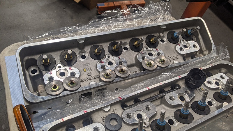
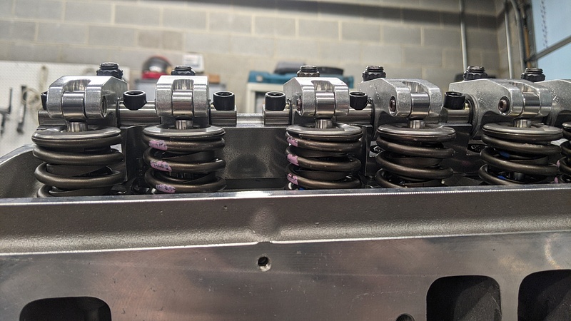
After that, I bolted on the heads and rockers:
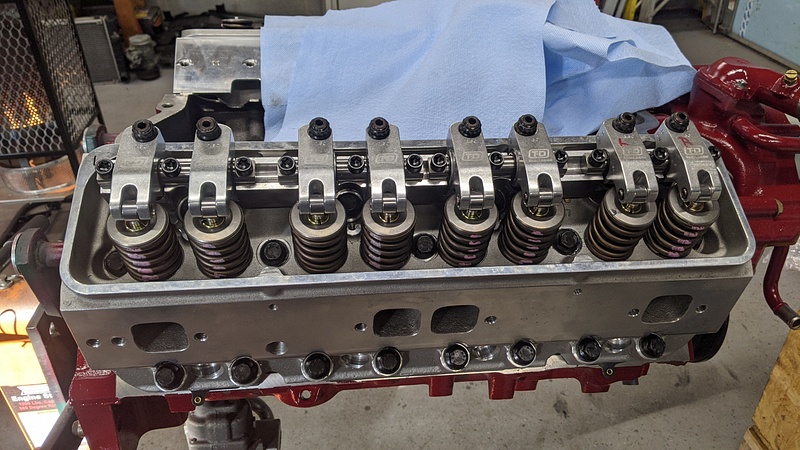
Good retainer clearance:
Now that the heads were installed and torqued down, I decided to doublecheck the needed pushrod lengths. The way that T&D says to measure for pushrods with their rockers is to turn the adjuster screw so that the pushrod cup is fully recessed into the rocker, and then turn the screw one full turn down, and measure from there. It also says to not turn the adjuster more than one full turn down or up from that position, or else you will cut off oil flow. Pushrod length was checked before when the heads weren't fully torqued. Upon checking again, the measurements were exactly 0.020" less than the previous measurements. The measurements came out to needing 7.300" on the exhaust, and 7.275" on the intake. I verified at all four corners, which I definitely wanted to do here with the two different head gasket thicknesses being used (.060" on Bank 1 and .053" on Bank 2). Unfortunately, during measuring, I noticed that the intake pushrod hugs the intake runner to the point that only a 5/16" pushrod could be used. So, I placed an order through LGM Racing for Manton 5/16, .116" wall, 210 degree pushrods and then played the waiting game with the post office.
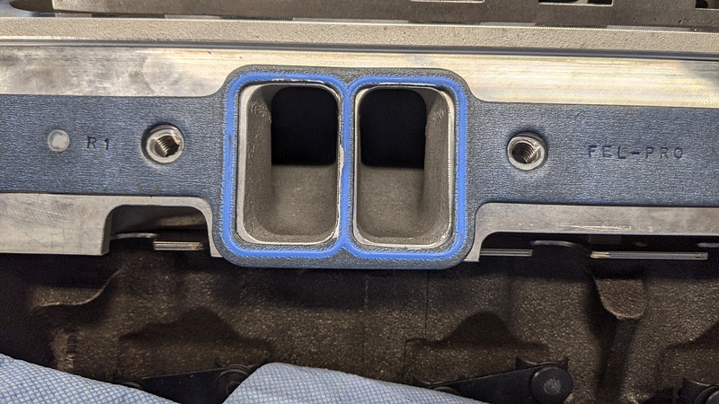
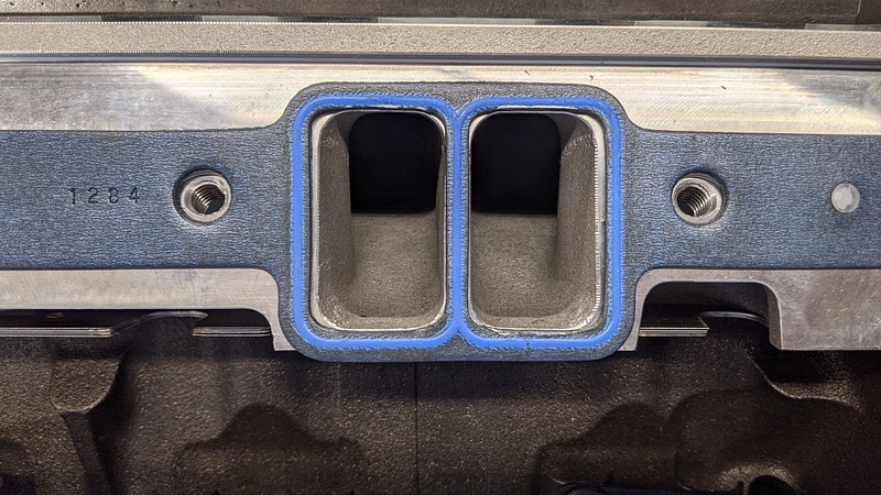
Before I got burned by the used AFR heads, I had purchased some Fel-Pro 1284 intake gaskets, as recommended by AFR. Of course, Dart recommended a Mr. Gasket part for their heads. I looked up the dimensions, and they were different, but I tried fitting up the Fel-Pros. Luckily, they only required minor touching up to work:
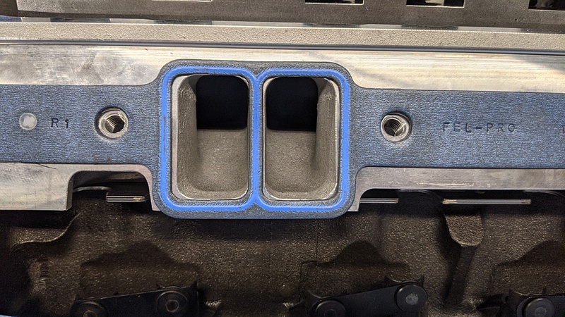
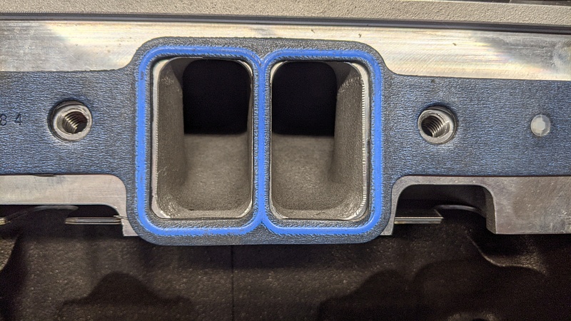
A little rotary action and we were in business:
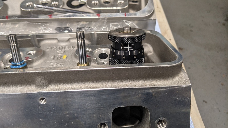
Another thing I wanted to check was lifter preload. Isky says that lifter preload should be set between .030" and .040". So, I found a bolt of the same thread pitch and diameter as the pushrod cup adjusters, and set up my dial indicator to see where I was. One full turn equated to .049" of preload:
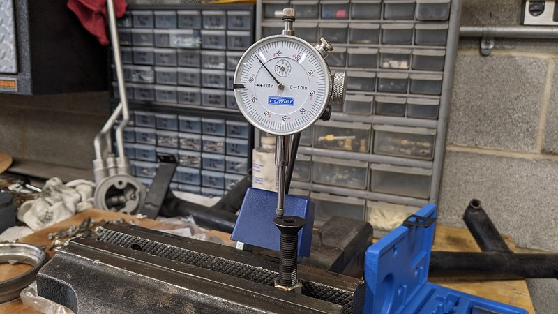
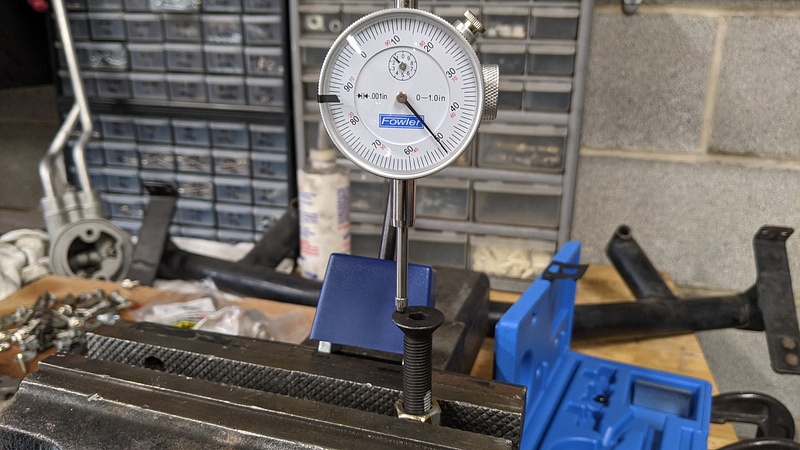
I found that .030" was right at a half turn, and .040" was right around 3/4" of a turn. So, once the pushrods arrived, I set everything up between a 1/2 and 3/4 turn. The exhaust length measurement came out to 7.305, so I went closer to 3/4" shooting for a total of .035", and the intakes true measurement was 7.272, so I went closer to a half turn since the 7.275 was .003" longer, so it would settle in the .033"-.035" range. Manton made it a little more interesting since they didn't mark the lengths on the pushrods, but rather bagged them separately. So, if I ever need to pull the pushrods, I will have to remember which ones are which. However, you can see that the T&D rockers lined up with the lifter cups very nicely. You can also see how the intake pushrods hug the runners. I would have needed a much heavier offset on the rocker and an offset lifter cup to fit a larger diameter pushrod with these heads.
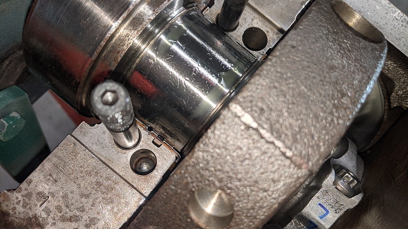
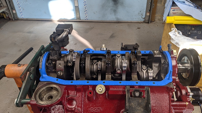
I also had to play the waiting game with the rear main seal. I noticed a groove was starting on the crank, so I ordered a seal from Enginetech (S5091) that has an offset lip to ride on a different part of the journal. It took a week and a half longer than anticipated to arrive. Once it arrived, I had to briefly pull the motor off the stand to install it and the pilot bearing. After that, I was finally able to install the oil pan.
These Fel-Pro oil pan gaskets are awesome:
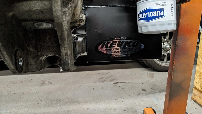
This is a Kevko oil pan for the V8 Monza/Vega with a slightly shallower sump:
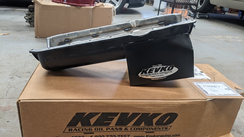
It has a built-in scraper, as well as baffling on the front and rear of the sump to prevent oil from sloshing up the walls:
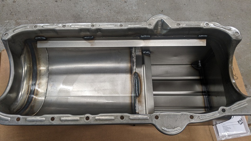
Right now, the ARP stud kit I got didn't have the stepped studs for the factory windage tray, and I'm not sure if the stock tray will even fit this pan without cutting the tray to all hell. With the scraper and baffles combined with the shorter stroke, I don't know if it is even worth it to try and get something in there. I'm exploring options now.
Crossmember clearance is tiiight. I am going to take some measurements and see if the steering rack will clear:
And my plan for using the factory oil cooler adapter has been foiled due to the pan's slight kick. Oh well, I have an adapter from Trans Dapt on order. More waiting. Huzzah:
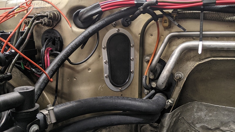
Since I had accidentally sold the firewall grommet for the wiring harness with the engine, I picked up a seal from Seals It. It has a nice, thick rubber seal that I'll cut for the engine harness when the time comes:
I also mocked up one of the Sanderson block hugger headers just to see how things were looking:
After painting the block, I had to wait on a new cam retainer plate before I could continue installation. Once that arrived, I was able to proceed. In order to get the 1X cam signal for the Terminator X, I picked up a signal kit from EFI Connections, which bolts to the nose of the camshaft. Since the cam was made for an LT1, and LT1s have an extended cam dowel to drive the Optispakr, I had to knock it in to make sure that it would not get picked up by the cam sensor. I realized after the fact that it didn't need to go flush with the base, but the instructions read that the dowel "should not protrude higher than the lowest part." I took that as the entire piece instead of the lowest point of the signal. Oh well, it certainly isn't going to interfere now.
EFI Connections 24x crank wheel:
Timing cover with the EFI Connections cam sensor housing that bolts in place of the Opti, and the Jegs underdrive pulley and balancer:
Once the cam was in, I dropped in the Isky short-travel lifters, made by Johnson. I also put the oil pump drive unit in just to get it off the work bench. I will have to remove it when it comes time to prime the motor with oil:
In the above picture, take notice of how the head gasket surrounds the pushrods. During mock-up for piston-valve clearance and such, I noticed that the 5/16" pushrods were rubbing in those areas. Since I was planning on using 11/32" or 3/8" pushrods, I did some clearancing. I initially tried tin snips, but that was leaving burrs, as well as requiring the gasket to be fanned out to cut each individual layer. I resorted to clamping the gasket down and using a rotary to cut. I still had to wipe and blow out each layer of debris:
After that, I bolted on the heads and rockers:
Good retainer clearance:
Now that the heads were installed and torqued down, I decided to doublecheck the needed pushrod lengths. The way that T&D says to measure for pushrods with their rockers is to turn the adjuster screw so that the pushrod cup is fully recessed into the rocker, and then turn the screw one full turn down, and measure from there. It also says to not turn the adjuster more than one full turn down or up from that position, or else you will cut off oil flow. Pushrod length was checked before when the heads weren't fully torqued. Upon checking again, the measurements were exactly 0.020" less than the previous measurements. The measurements came out to needing 7.300" on the exhaust, and 7.275" on the intake. I verified at all four corners, which I definitely wanted to do here with the two different head gasket thicknesses being used (.060" on Bank 1 and .053" on Bank 2). Unfortunately, during measuring, I noticed that the intake pushrod hugs the intake runner to the point that only a 5/16" pushrod could be used. So, I placed an order through LGM Racing for Manton 5/16, .116" wall, 210 degree pushrods and then played the waiting game with the post office.
Before I got burned by the used AFR heads, I had purchased some Fel-Pro 1284 intake gaskets, as recommended by AFR. Of course, Dart recommended a Mr. Gasket part for their heads. I looked up the dimensions, and they were different, but I tried fitting up the Fel-Pros. Luckily, they only required minor touching up to work:
A little rotary action and we were in business:
Another thing I wanted to check was lifter preload. Isky says that lifter preload should be set between .030" and .040". So, I found a bolt of the same thread pitch and diameter as the pushrod cup adjusters, and set up my dial indicator to see where I was. One full turn equated to .049" of preload:
I found that .030" was right at a half turn, and .040" was right around 3/4" of a turn. So, once the pushrods arrived, I set everything up between a 1/2 and 3/4 turn. The exhaust length measurement came out to 7.305, so I went closer to 3/4" shooting for a total of .035", and the intakes true measurement was 7.272, so I went closer to a half turn since the 7.275 was .003" longer, so it would settle in the .033"-.035" range. Manton made it a little more interesting since they didn't mark the lengths on the pushrods, but rather bagged them separately. So, if I ever need to pull the pushrods, I will have to remember which ones are which. However, you can see that the T&D rockers lined up with the lifter cups very nicely. You can also see how the intake pushrods hug the runners. I would have needed a much heavier offset on the rocker and an offset lifter cup to fit a larger diameter pushrod with these heads.
I also had to play the waiting game with the rear main seal. I noticed a groove was starting on the crank, so I ordered a seal from Enginetech (S5091) that has an offset lip to ride on a different part of the journal. It took a week and a half longer than anticipated to arrive. Once it arrived, I had to briefly pull the motor off the stand to install it and the pilot bearing. After that, I was finally able to install the oil pan.
These Fel-Pro oil pan gaskets are awesome:
This is a Kevko oil pan for the V8 Monza/Vega with a slightly shallower sump:
It has a built-in scraper, as well as baffling on the front and rear of the sump to prevent oil from sloshing up the walls:
Right now, the ARP stud kit I got didn't have the stepped studs for the factory windage tray, and I'm not sure if the stock tray will even fit this pan without cutting the tray to all hell. With the scraper and baffles combined with the shorter stroke, I don't know if it is even worth it to try and get something in there. I'm exploring options now.
Crossmember clearance is tiiight. I am going to take some measurements and see if the steering rack will clear:
And my plan for using the factory oil cooler adapter has been foiled due to the pan's slight kick. Oh well, I have an adapter from Trans Dapt on order. More waiting. Huzzah:
Since I had accidentally sold the firewall grommet for the wiring harness with the engine, I picked up a seal from Seals It. It has a nice, thick rubber seal that I'll cut for the engine harness when the time comes:
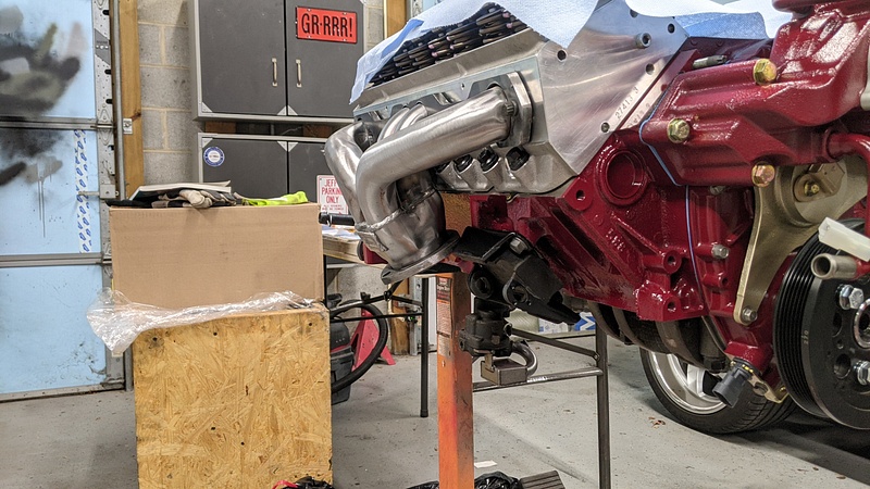
I also mocked up one of the Sanderson block hugger headers just to see how things were looking:
-
Huckleberry
- Senior Chief Patty Officer
- Posts: 2426
- Joined: Tue Nov 20, 2018 9:10 am
- Drives: 2004 GTO
- Location: Hi. I'm in Delaware.
Indeed. That's two cars you need to photograph. Maybe five if you include the GTO, El Camino, and Rabbit. I haven't posted the pictures from those builds yet.[user not found] wrote: ↑Tue Jan 12, 2021 10:18 am
When this is done, I want an opportunity to photograph the car and give it some justice.
-
Huckleberry
- Senior Chief Patty Officer
- Posts: 2426
- Joined: Tue Nov 20, 2018 9:10 am
- Drives: 2004 GTO
- Location: Hi. I'm in Delaware.
Update time! It has been a while. USPS has been slow, and progress has suffered as a result.
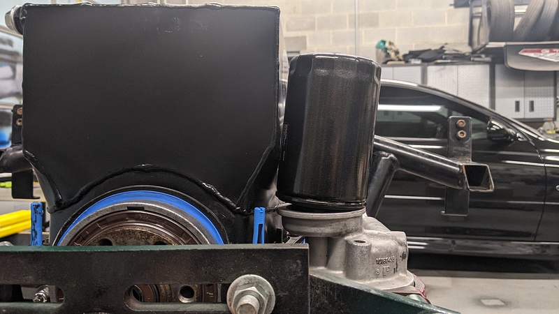
I ordered a sandwich adapter from Trans Dapt for the oil cooler. This one isn't affected by the pan kicking out:
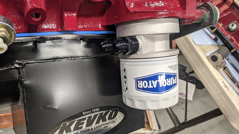
A little maroon paint and good to go:
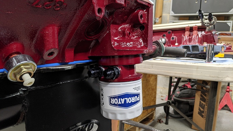
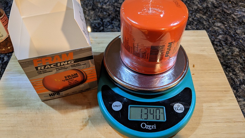
The cheap Purolator oil filter is for break-in. I have a Fram HP8 racing filter to go on afterwards. Speaking of which, those filters have some heft to them:
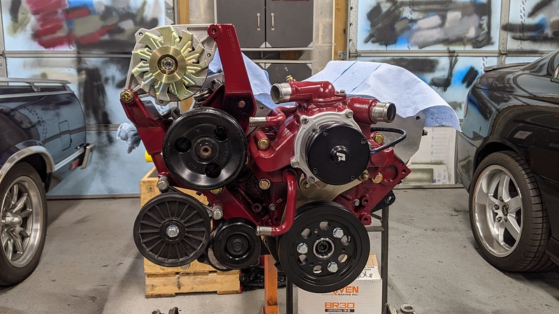
When it comes to the LT1s, due to the water pump being driven by the camshaft gear, the accessory brackets are specific to the LT1. I had come across an aftermarket setup that uses just the alternator and the power steering pump and had the idea of using the stock 944 AC compressor on the driver's side. Unfortunately, after mocking things up, that idea was not going to fly since the compressor interfered with the motor mount. It's a shame because I do like this configuration.
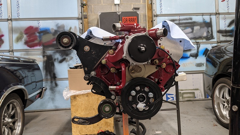
So, I acquired an F-Body bracket. The guy I bought it from was kind enough to include an AC delete pulley, power steering pump, tensioner, and serpentine belt for a lower price than what other clowns wanted for just the bracket.
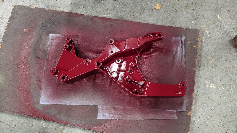
The motor mount bracket is something I acquired used since every company that used to make the adapters for SBC/LT1 has since abandoned the platforms for going entirely LS. It has made certain aspects of this project a challenge, but it goes to show how cookie-cutter a lot of these things have become. This bracket is different from the other ones I have seen as it utilizes two of the crossmember mounts and the sway bar mounts to attach to the car.
All of the other adapters I have seen utilize the original motor mount positions. I like this design better because it doesn't put the mounts at such extreme angles.

Anyways, I removed the crossmember and bolted the two together to mockup on the engine stand for oil pan clearance.
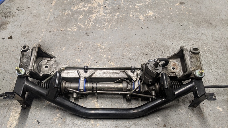
The sump is going to give me excellent ground clearance, and there is enough space between the sump and crossmember that I am going to run the power steering line from the pump to the hydroboost through that space.
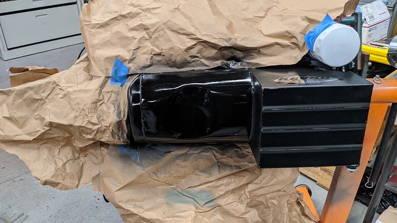
The oil pan needed a little massaging to clear the steering rack:

A quick shot of black and nothing ever happened:
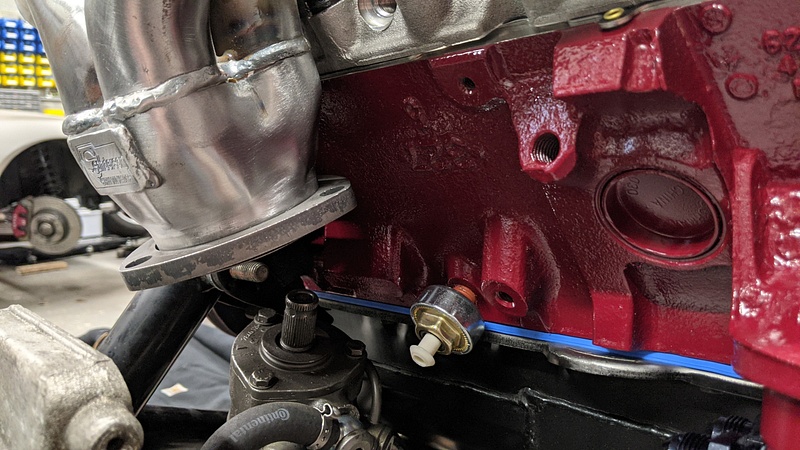
Unfortunately, the driver's side header dumps right onto the steering rack:
I spent some time searching for different headers with 1 3/4" primaries. I thought I had found a winner, but it became the same issue with the two center primaries:
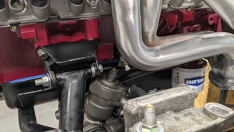
Yes, I could cut the tubes and move things around, but I honestly don't feel it is worth the effort. If I'm going to weld up some headers, then I am going to do a tri-y design. So, I ordered one Sanderson CC2 and one Sanderson CC90. They are 1 5/8" primaries, but are proven to fit the chassis. Once I get the car running and things sorted, I'll see how I feel down the line about different headers.
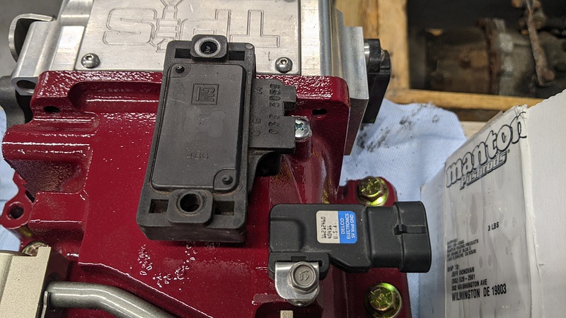
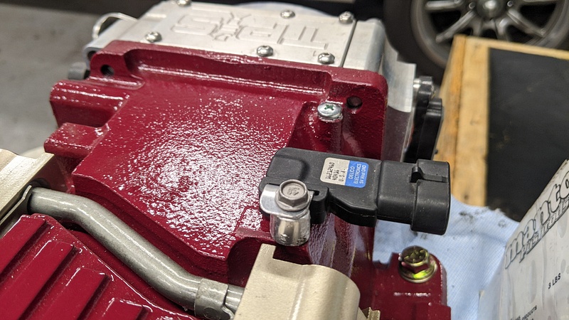
And since I had an LS6 MAP sensor laying around, I made up a little bracket to replace the behemoth LT1 sensor:
I ordered a sandwich adapter from Trans Dapt for the oil cooler. This one isn't affected by the pan kicking out:
A little maroon paint and good to go:
The cheap Purolator oil filter is for break-in. I have a Fram HP8 racing filter to go on afterwards. Speaking of which, those filters have some heft to them:
When it comes to the LT1s, due to the water pump being driven by the camshaft gear, the accessory brackets are specific to the LT1. I had come across an aftermarket setup that uses just the alternator and the power steering pump and had the idea of using the stock 944 AC compressor on the driver's side. Unfortunately, after mocking things up, that idea was not going to fly since the compressor interfered with the motor mount. It's a shame because I do like this configuration.
So, I acquired an F-Body bracket. The guy I bought it from was kind enough to include an AC delete pulley, power steering pump, tensioner, and serpentine belt for a lower price than what other clowns wanted for just the bracket.
The motor mount bracket is something I acquired used since every company that used to make the adapters for SBC/LT1 has since abandoned the platforms for going entirely LS. It has made certain aspects of this project a challenge, but it goes to show how cookie-cutter a lot of these things have become. This bracket is different from the other ones I have seen as it utilizes two of the crossmember mounts and the sway bar mounts to attach to the car.
All of the other adapters I have seen utilize the original motor mount positions. I like this design better because it doesn't put the mounts at such extreme angles.
Anyways, I removed the crossmember and bolted the two together to mockup on the engine stand for oil pan clearance.
The sump is going to give me excellent ground clearance, and there is enough space between the sump and crossmember that I am going to run the power steering line from the pump to the hydroboost through that space.
The oil pan needed a little massaging to clear the steering rack:
A quick shot of black and nothing ever happened:
Unfortunately, the driver's side header dumps right onto the steering rack:
I spent some time searching for different headers with 1 3/4" primaries. I thought I had found a winner, but it became the same issue with the two center primaries:
Yes, I could cut the tubes and move things around, but I honestly don't feel it is worth the effort. If I'm going to weld up some headers, then I am going to do a tri-y design. So, I ordered one Sanderson CC2 and one Sanderson CC90. They are 1 5/8" primaries, but are proven to fit the chassis. Once I get the car running and things sorted, I'll see how I feel down the line about different headers.
And since I had an LS6 MAP sensor laying around, I made up a little bracket to replace the behemoth LT1 sensor:
-
ChrisoftheNorth
- Moderator
- Posts: 47112
- Joined: Thu Nov 03, 2016 6:10 am
- Drives: 4R
Man, I love these updates.Huckleberry wrote: ↑Mon Feb 08, 2021 9:12 pm Update time! It has been a while. USPS has been slow, and progress has suffered as a result.
I ordered a sandwich adapter from Trans Dapt for the oil cooler. This one isn't affected by the pan kicking out:
A little maroon paint and good to go:
The cheap Purolator oil filter is for break-in. I have a Fram HP8 racing filter to go on afterwards. Speaking of which, those filters have some heft to them:
When it comes to the LT1s, due to the water pump being driven by the camshaft gear, the accessory brackets are specific to the LT1. I had come across an aftermarket setup that uses just the alternator and the power steering pump and had the idea of using the stock 944 AC compressor on the driver's side. Unfortunately, after mocking things up, that idea was not going to fly since the compressor interfered with the motor mount. It's a shame because I do like this configuration.
So, I acquired an F-Body bracket. The guy I bought it from was kind enough to include an AC delete pulley, power steering pump, tensioner, and serpentine belt for a lower price than what other clowns wanted for just the bracket.
The motor mount bracket is something I acquired used since every company that used to make the adapters for SBC/LT1 has since abandoned the platforms for going entirely LS. It has made certain aspects of this project a challenge, but it goes to show how cookie-cutter a lot of these things have become. This bracket is different from the other ones I have seen as it utilizes two of the crossmember mounts and the sway bar mounts to attach to the car.
All of the other adapters I have seen utilize the original motor mount positions. I like this design better because it doesn't put the mounts at such extreme angles.
Anyways, I removed the crossmember and bolted the two together to mockup on the engine stand for oil pan clearance.
The sump is going to give me excellent ground clearance, and there is enough space between the sump and crossmember that I am going to run the power steering line from the pump to the hydroboost through that space.
The oil pan needed a little massaging to clear the steering rack:
A quick shot of black and nothing ever happened:
Unfortunately, the driver's side header dumps right onto the steering rack:
I spent some time searching for different headers with 1 3/4" primaries. I thought I had found a winner, but it became the same issue with the two center primaries:
Yes, I could cut the tubes and move things around, but I honestly don't feel it is worth the effort. If I'm going to weld up some headers, then I am going to do a tri-y design. So, I ordered one Sanderson CC2 and one Sanderson CC90. They are 1 5/8" primaries, but are proven to fit the chassis. Once I get the car running and things sorted, I'll see how I feel down the line about different headers.
And since I had an LS6 MAP sensor laying around, I made up a little bracket to replace the behemoth LT1 sensor:
I doubt you're going to suffer much performance from smaller primary headers, but I sure would like to see you weld up a tri-y set.
 as always.
Desertbreh wrote: ↑Tue Oct 10, 2017 6:40 pm My guess would be that Chris took some time off because he has read the dialogue on this page 1,345 times and decided to spend some of his free time doing something besides beating a horse to death.
-
Huckleberry
- Senior Chief Patty Officer
- Posts: 2426
- Joined: Tue Nov 20, 2018 9:10 am
- Drives: 2004 GTO
- Location: Hi. I'm in Delaware.
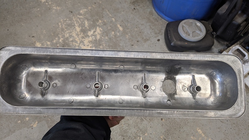
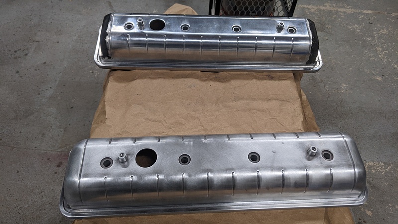
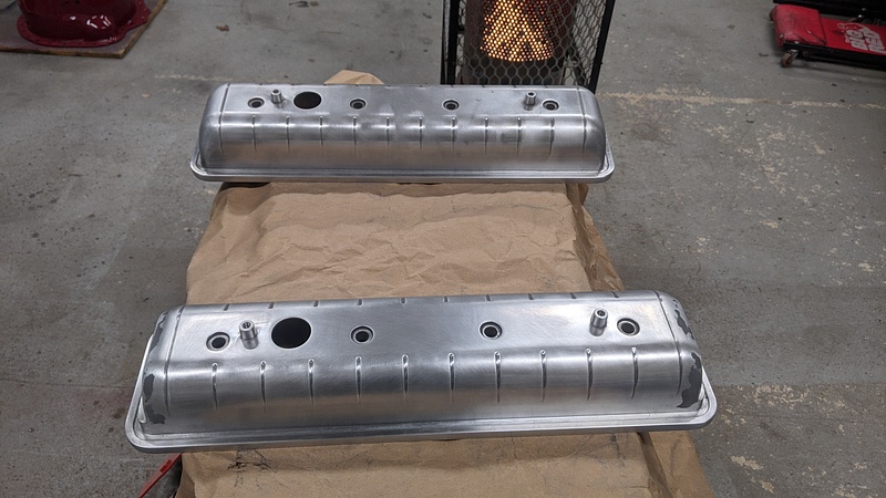
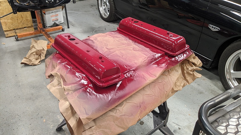
The final ghost from the AFR F'ed in the A adventure is the valve covers. The AFR heads used perimeter bolt valve covers, which is what I had purchased. The Dart heads use center bolt valve covers, and since I am using shaft rockers, I couldn't just buy the adapters. So, that means that the valve covers I made can't be used and will be sitting on the shelf:
So, I searched the interwebz for some nice centerbolt valve covers, and this is where I have to say, "Thank God for Boomers." I came across a company called Technostalgia, and they make a set of covers that they call the "Fauxmobile Covers." Basically, they are centerbolt covers for those people who want their Chevy small block to look like an Oldsmobile engine. They even come complete with "Oldsmobile Rocket" decals.

These piqued my interest for two reasons: the ability to still have a personally styled valve cover and the fact that they incorporate the plug wire looms. So, I ordered the natural aluminum pair. And after a month of backorder, it was revealed that the natural valve covers were discontinued because of course the Boomers are only buying the polished sets. Fucking Boomers, man. So, I settled for the polished set, which meant I now had to take extra steps to paint them. At least Speedway knocked money off since I told them that the polished finish was absolutely worthless to me. Upon receipt, I'm glad that took money off, because the polished finish was absolutely worthless.
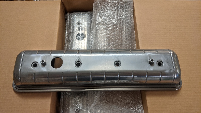
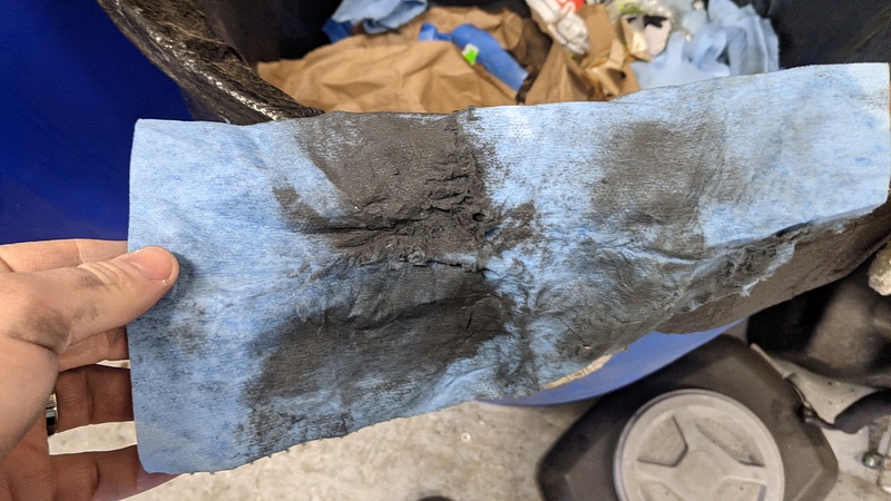
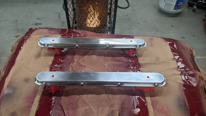
And this is why you clean your parts before installing them. These covers were insanely dirty. I don't even know how these were allowed to leave the factory like this:
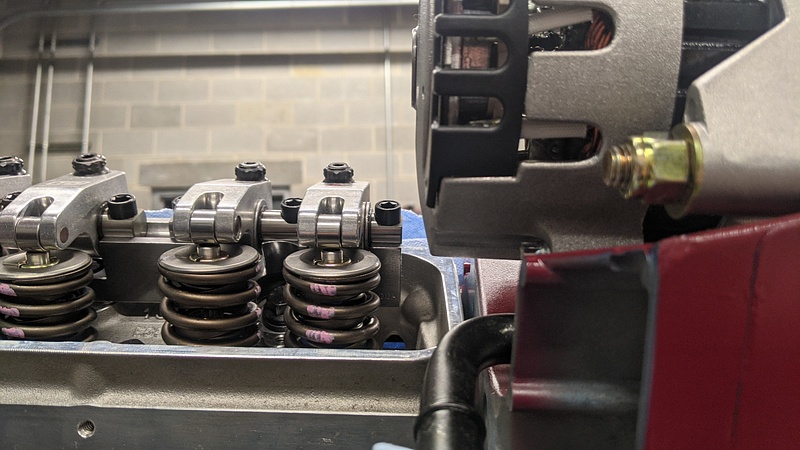
Another issue with LT1s is that the alternator interferes with the passenger side valve cover. This is why the factory covers are notched. The stock alternator is a CS144 with a 7.25" bolt spread. I bought a smaller CS130 with the same bolt spread hoping that it would give me the needed clearance. It did not.
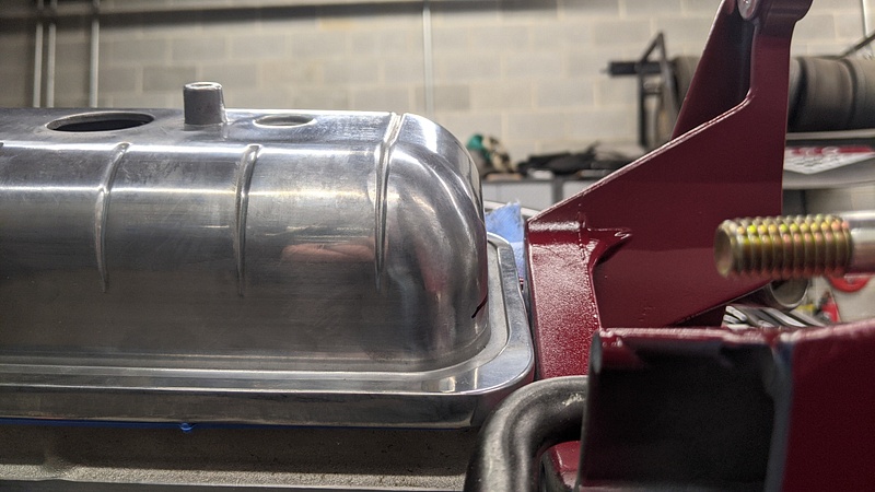
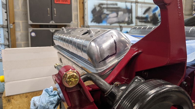
So, I contacted a friend of a friend to help with notching since I don't have the ability to weld aluminum. I provided some measurements, and he made a cut with his band saw while I took the grinder to back of my new alternator because I like to party:
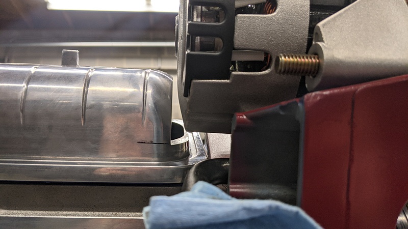
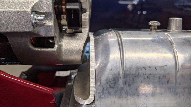
It was at this point that I realized, in my being much concerned with the alternator clearing, I missed the fact that though they are called "center bolt covers," those bolt holes ain't exactly in the center. And since I had placed the oil cap hole towards the front of the motor, that meant that the valve cover was backwards...which also meant that the wrong end had just been cut.

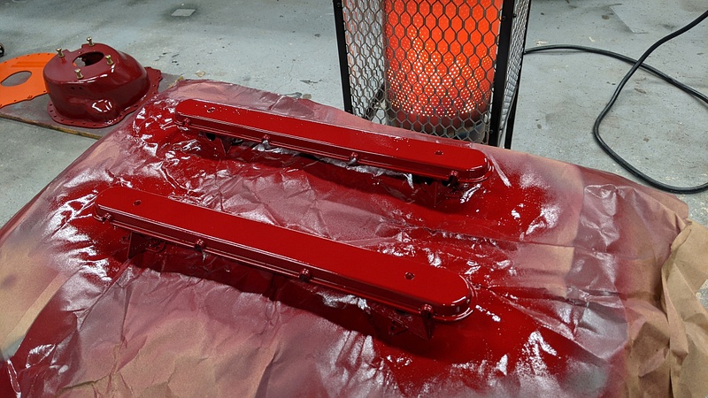
So, both sides had to get cut and welded. Once that was done, I was able to get back to painting. The welds were ground smooth, and then I filled in the imperfections with JB Weld. I also took red Scotch Brite to knock off whatever "polish" there was.
I sanded the JB Weld with 220:
Etching primer. You can see my arsenal of rattle cans on the floor:
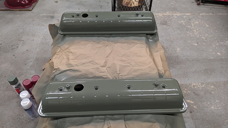
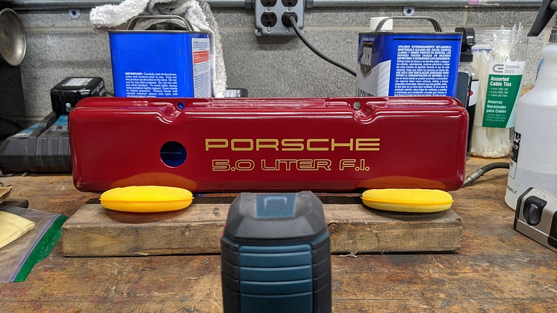
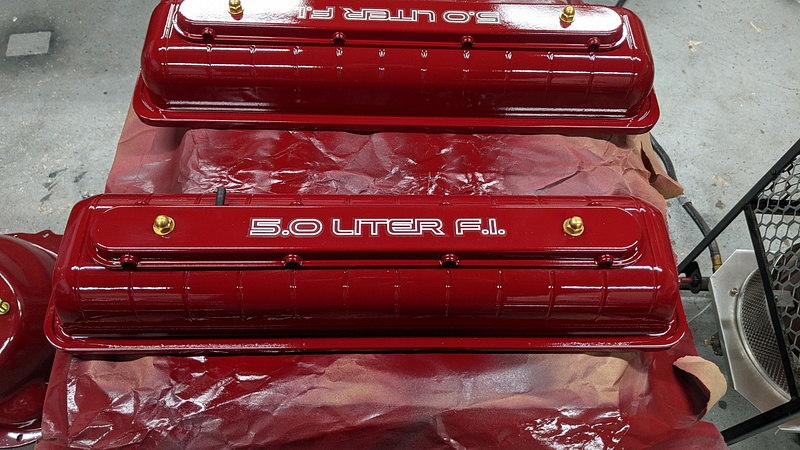
Base coat:
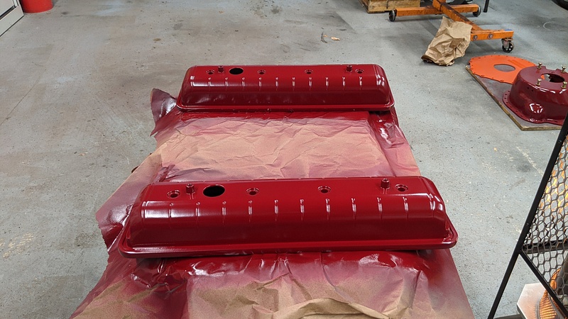
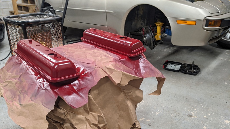
Clear coat:
Then I did the same with the wire looms:
And bada-boom:
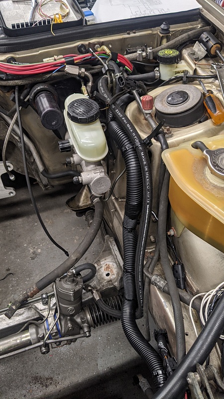
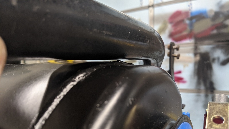
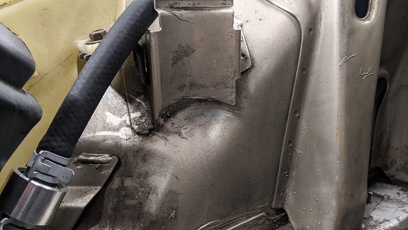
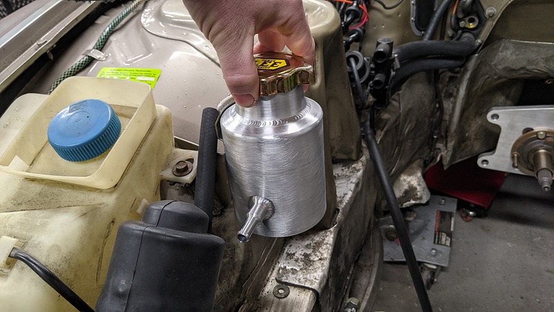
The latest arrival (it literally arrived today) is a custom power steering reservoir from Lee's Power Steering. With these hydroboost setups, a lot of people have complained about feeling pulsating in the steering wheel, and it is attributed to them having teed the hydroboost and steering rack returns together. I searched for a bit, and finally came across Lee's. Their custom reservoirs were damn close in size to the factory 944 reservoir.
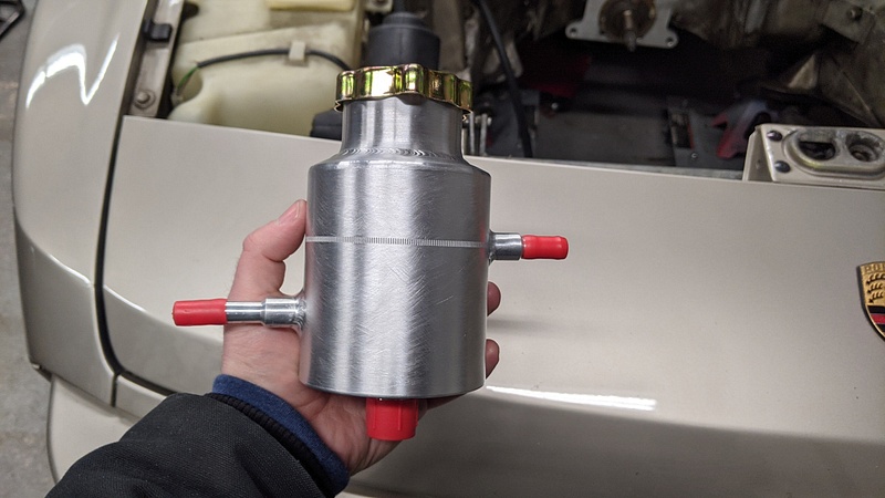
Honestly, if it wasn't for that tall neck, it would have fit in the stock bracket without issue. However, I think hood clearance may be a problem, so I wanted the bracket to sit a little lower. The stock bracket has a lip that kicks out and prevents the reservoir from sitting lower. So, I cut the lip off, and with a few taps on the wheel wheel, she sits in there nicely. I'll clean things up tomorrow.
So, I searched the interwebz for some nice centerbolt valve covers, and this is where I have to say, "Thank God for Boomers." I came across a company called Technostalgia, and they make a set of covers that they call the "Fauxmobile Covers." Basically, they are centerbolt covers for those people who want their Chevy small block to look like an Oldsmobile engine. They even come complete with "Oldsmobile Rocket" decals.
These piqued my interest for two reasons: the ability to still have a personally styled valve cover and the fact that they incorporate the plug wire looms. So, I ordered the natural aluminum pair. And after a month of backorder, it was revealed that the natural valve covers were discontinued because of course the Boomers are only buying the polished sets. Fucking Boomers, man. So, I settled for the polished set, which meant I now had to take extra steps to paint them. At least Speedway knocked money off since I told them that the polished finish was absolutely worthless to me. Upon receipt, I'm glad that took money off, because the polished finish was absolutely worthless.
And this is why you clean your parts before installing them. These covers were insanely dirty. I don't even know how these were allowed to leave the factory like this:
Another issue with LT1s is that the alternator interferes with the passenger side valve cover. This is why the factory covers are notched. The stock alternator is a CS144 with a 7.25" bolt spread. I bought a smaller CS130 with the same bolt spread hoping that it would give me the needed clearance. It did not.
So, I contacted a friend of a friend to help with notching since I don't have the ability to weld aluminum. I provided some measurements, and he made a cut with his band saw while I took the grinder to back of my new alternator because I like to party:
It was at this point that I realized, in my being much concerned with the alternator clearing, I missed the fact that though they are called "center bolt covers," those bolt holes ain't exactly in the center. And since I had placed the oil cap hole towards the front of the motor, that meant that the valve cover was backwards...which also meant that the wrong end had just been cut.
So, both sides had to get cut and welded. Once that was done, I was able to get back to painting. The welds were ground smooth, and then I filled in the imperfections with JB Weld. I also took red Scotch Brite to knock off whatever "polish" there was.
I sanded the JB Weld with 220:
Etching primer. You can see my arsenal of rattle cans on the floor:
Base coat:
Clear coat:
Then I did the same with the wire looms:
And bada-boom:
The latest arrival (it literally arrived today) is a custom power steering reservoir from Lee's Power Steering. With these hydroboost setups, a lot of people have complained about feeling pulsating in the steering wheel, and it is attributed to them having teed the hydroboost and steering rack returns together. I searched for a bit, and finally came across Lee's. Their custom reservoirs were damn close in size to the factory 944 reservoir.
Honestly, if it wasn't for that tall neck, it would have fit in the stock bracket without issue. However, I think hood clearance may be a problem, so I wanted the bracket to sit a little lower. The stock bracket has a lip that kicks out and prevents the reservoir from sitting lower. So, I cut the lip off, and with a few taps on the wheel wheel, she sits in there nicely. I'll clean things up tomorrow.
-
Huckleberry
- Senior Chief Patty Officer
- Posts: 2426
- Joined: Tue Nov 20, 2018 9:10 am
- Drives: 2004 GTO
- Location: Hi. I'm in Delaware.
It would be the first set of headers I ever built from scratch. I think that would be in the second phase depending on how this motor behaves. The primaries are damn short on these new headers, so the smaller diameter may help with the low-end. The rest of the exhaust is going to be built by me. It will be 2.5" tubes off the headers merging into a single 3" pipe all the way out the back. I have a single 3" Magnaflow catalytic converter, and I'm currently up in the air on a muffler going between a 6" round or a 5x8 oval. Either design will be straight-through.
-
ChrisoftheNorth
- Moderator
- Posts: 47112
- Joined: Thu Nov 03, 2016 6:10 am
- Drives: 4R
With short primaries, tube diameter is even less important right? Especially going with 2.5" on either side into 3". This thing is going to soundHuckleberry wrote: ↑Mon Feb 08, 2021 10:04 pmIt would be the first set of headers I ever built from scratch. I think that would be in the second phase depending on how this motor behaves. The primaries are damn short on these new headers, so the smaller diameter may help with the low-end. The rest of the exhaust is going to be built by me. It will be 2.5" tubes off the headers merging into a single 3" pipe all the way out the back. I have a single 3" Magnaflow catalytic converter, and I'm currently up in the air on a muffler going between a 6" round or a 5x8 oval. Either design will be straight-through.
Desertbreh wrote: ↑Tue Oct 10, 2017 6:40 pm My guess would be that Chris took some time off because he has read the dialogue on this page 1,345 times and decided to spend some of his free time doing something besides beating a horse to death.
-
Huckleberry
- Senior Chief Patty Officer
- Posts: 2426
- Joined: Tue Nov 20, 2018 9:10 am
- Drives: 2004 GTO
- Location: Hi. I'm in Delaware.
Yeah, the short primary length should help with making power in the upper RPMs. I'm leaning towards the oval muffler, too. May even go with a 5x11 so it sounds a bit more subdued than it really is.Detroit wrote: ↑Tue Feb 09, 2021 12:32 pmWith short primaries, tube diameter is even less important right? Especially going with 2.5" on either side into 3". This thing is going to soundHuckleberry wrote: ↑Mon Feb 08, 2021 10:04 pm
It would be the first set of headers I ever built from scratch. I think that would be in the second phase depending on how this motor behaves. The primaries are damn short on these new headers, so the smaller diameter may help with the low-end. The rest of the exhaust is going to be built by me. It will be 2.5" tubes off the headers merging into a single 3" pipe all the way out the back. I have a single 3" Magnaflow catalytic converter, and I'm currently up in the air on a muffler going between a 6" round or a 5x8 oval. Either design will be straight-through.and I vote for a 5x8 oval in the stock location with a tip mounted right to it. Muffler is slightly visible, will look a tad more sleeper like that.

