It's been a minute. I wanted to save on updating until the motor was in the car, but unfortunately, that isn't the case just yet. We are currently in the process of downsizing the in-laws so that they have a house that they can afford and physically maintain. And since the wife's father has been a hoarder his entire life, we have just finished loading up the third 30-yard dumpster and will be moving onto a fourth. Needless to say, that entire process has become a time suck, as has the continued shipping delays thanks to COVID and online shopping having become the coping mechanism of choice for the entire world.
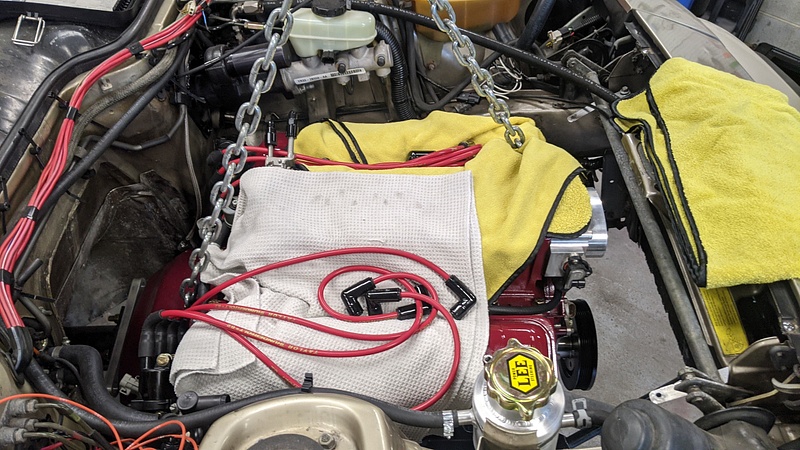
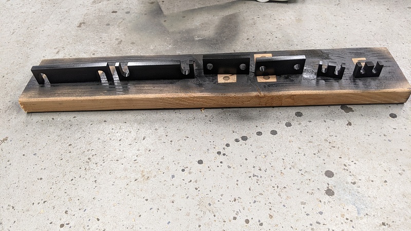
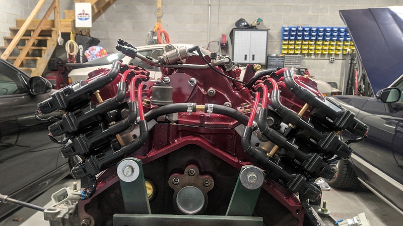
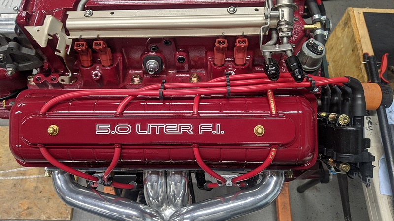
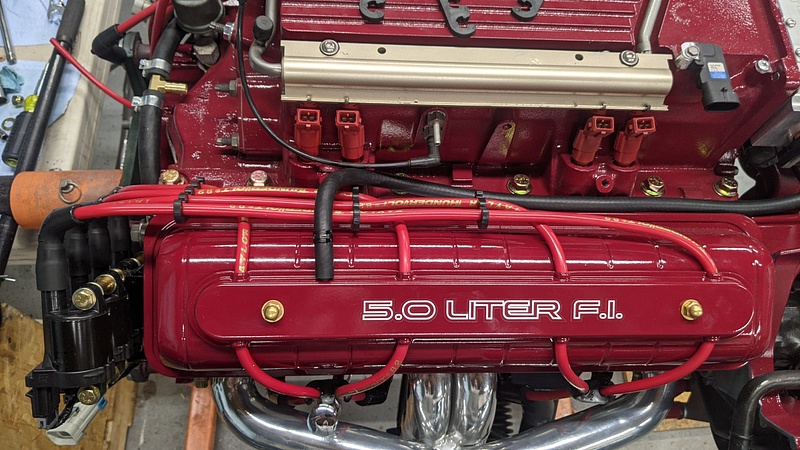
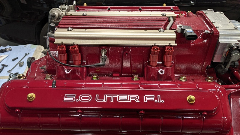
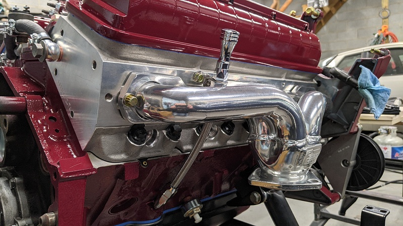
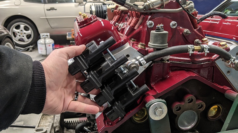
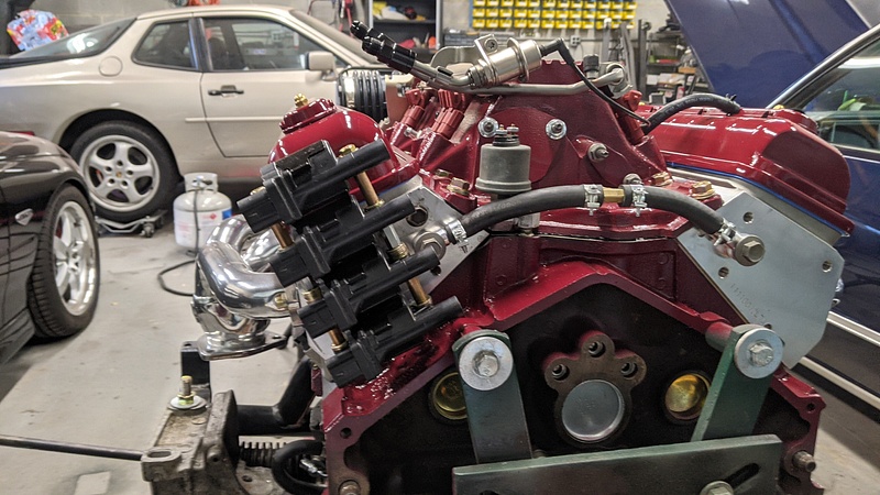
Anyways, I finished the coil pack mounts. As it turns out, I couldn't just flip the one template I made and needed to make an entirely different template for the passenger side head. Go figure.
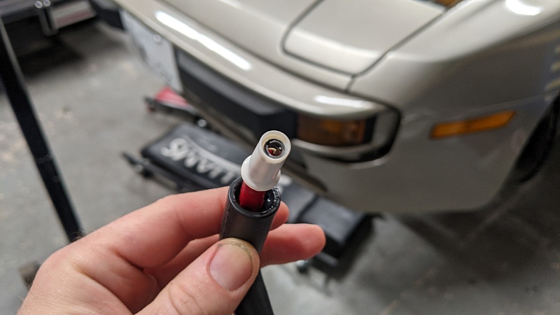
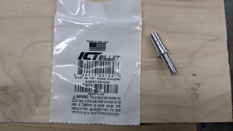
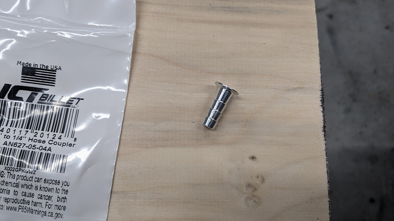
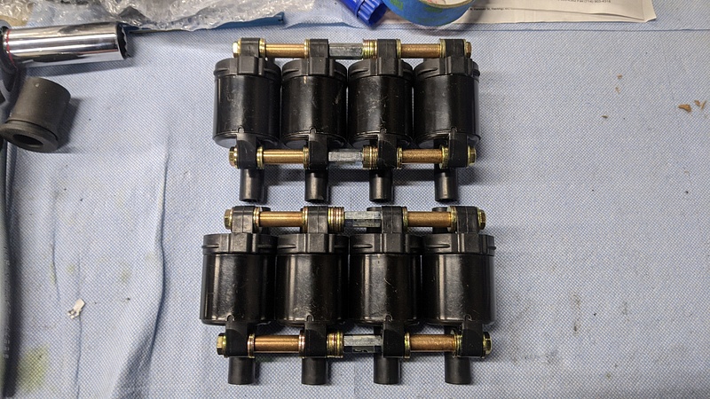
The plug wire kit from Taylor that I picked up came with 45* boots for the ignition coils. When I was mocking things up, I didn't like how the wires were going to lay, so I placed an order for 90* boots. Once those came in, the second issue I had was that Taylor called these "universal LS wire kits," and it would appear that they felt universal wire assembly instructions would suffice. The problem is that the universal instructions don't include any mention of these bastards:
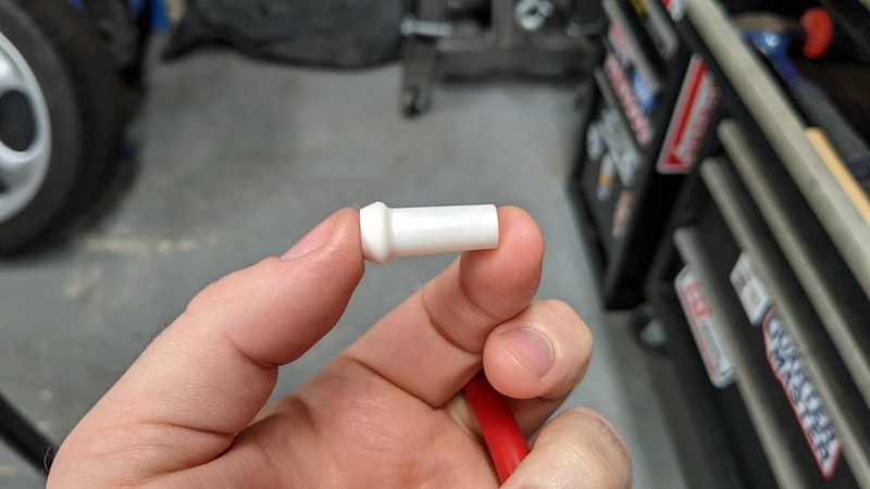
After trying to figure out where these pieces lie in the puzzle, I stumbled upon the answer in, of all places, a Summit Racing comment. The comment even included a hand-drawn diagram of how these things go together. I promptly responded to that comment thanking the person for providing what Taylor failed to provide, and went about assembling the wires. The first wire was the toughest with the most trial and error. I started with the wire that required the longest length, because if I messed up, I could trim the wire down and use it for a cylinder requiring less length. Here is the process that worked for me:
I packed the boot full of dielectric grease. I tried silicone spray at first, and it did not work. Dielectric grease was the ticket to success.
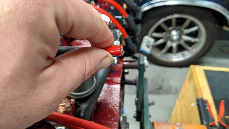
I then inserted the wire into the boot. Since it is a 90* boot, I straightened it out to give the wire as straight of a path as possible. On some of the wires, I would receive resistance, at which point I would pull the wire back out, pack the boot full of more grease, and then push it on through. **PINTEREST LIFE HACK** - The wire will push out a bunch of grease. Just wipe off that grease and apply it to the next boot.
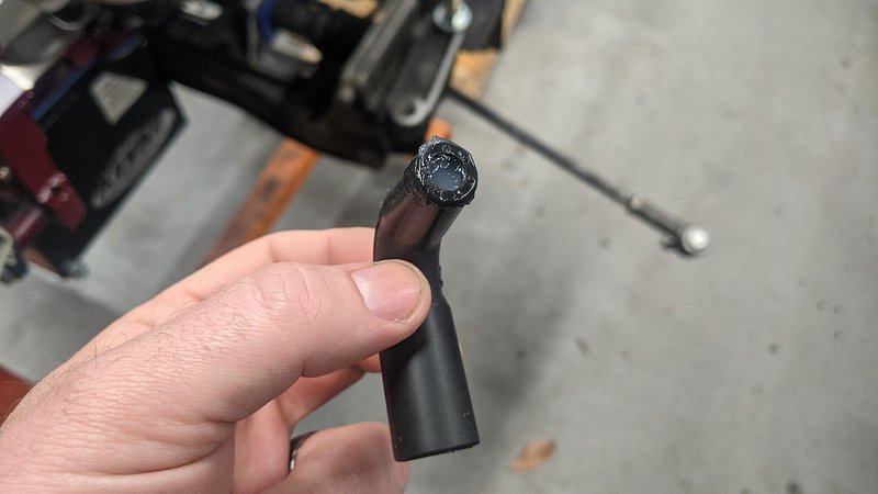
I used some wire strippers and cut the insulation back by about an inch and folded the conductor over:
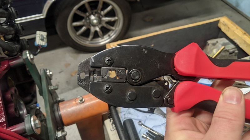
And with some 8mm wire crimpers I found online, I crimped the terminal on:
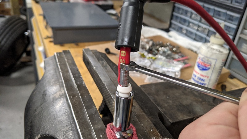
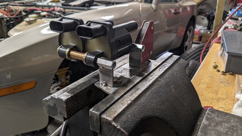
The fun part was installing the plastic guide. It is an extremely tight fit. The approach I wound up settling on is similar to installing an oil pick-up tube on an older oil pump. I put the plastic guide in a socket and secured it in my vise. I then used a wrench that wrapped around the wire while gripping the end of the crimped terminal, and then I used a hammer to tap the terminal into the plastic guide. Sometimes, the wire's insulation would begin to bunch by the crimp. In those cases, I would use a small flathead to push the insulation into the guide, or I would take a razor and trim it.
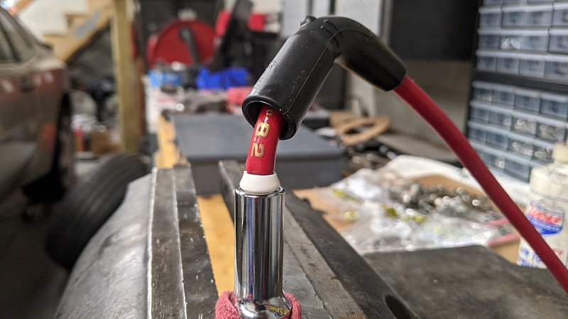
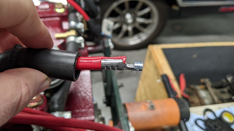
The terminal will bottom out into a lip on the guide:
And then there should be enough remaining grease to allow you to easily pull the boot over. You will feel the guide fall into place in the boot:
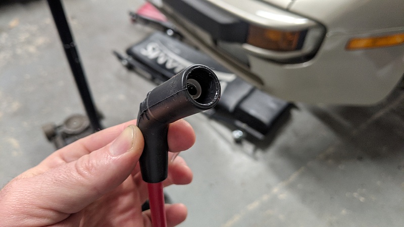
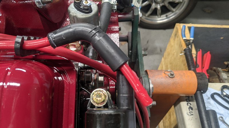
Repeat the process seven more times, and you'll have some plug wires:
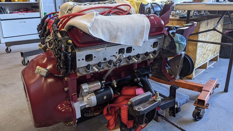
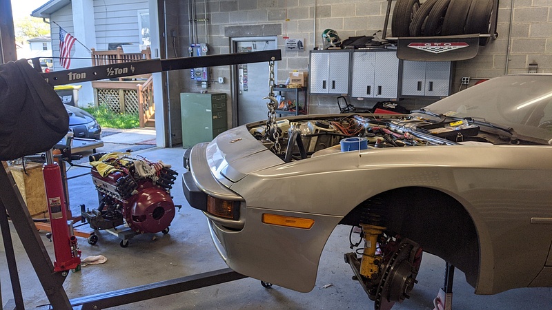
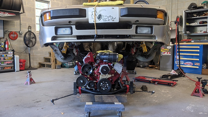
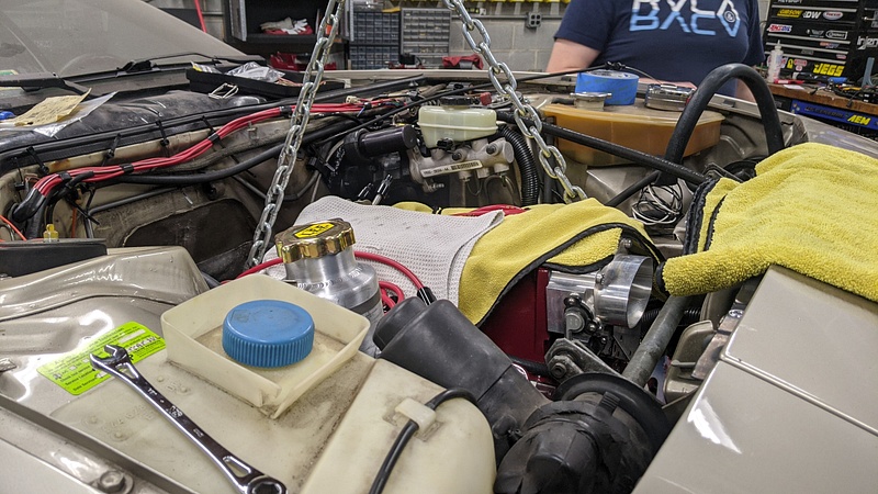
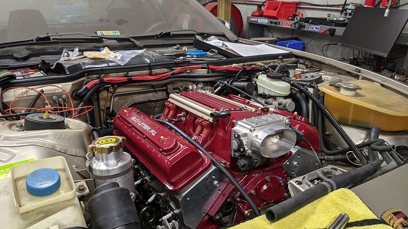
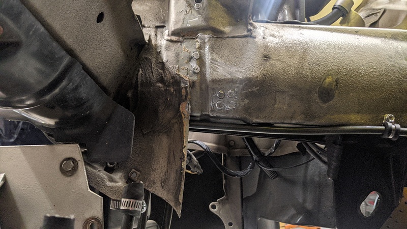
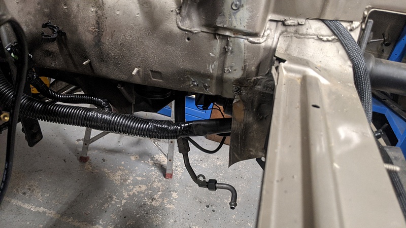
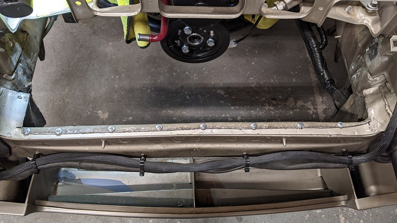
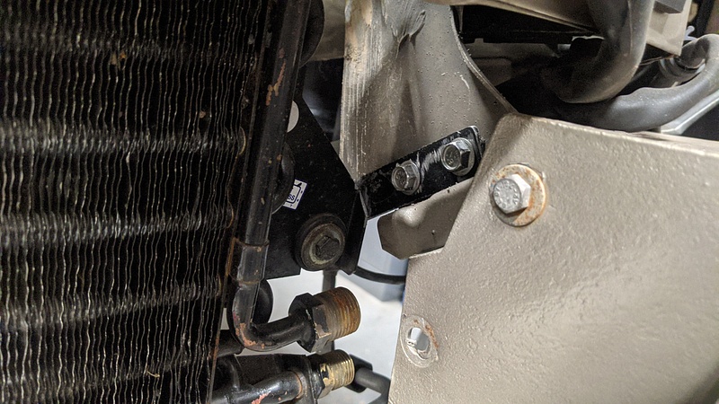
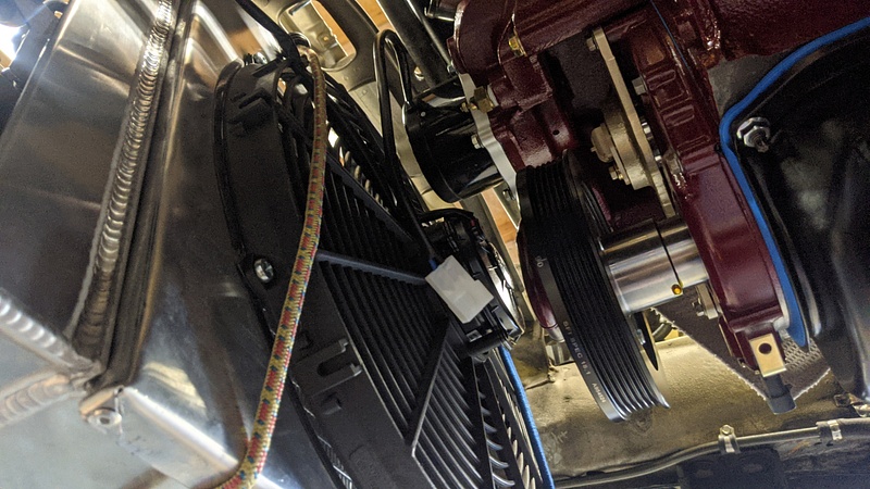
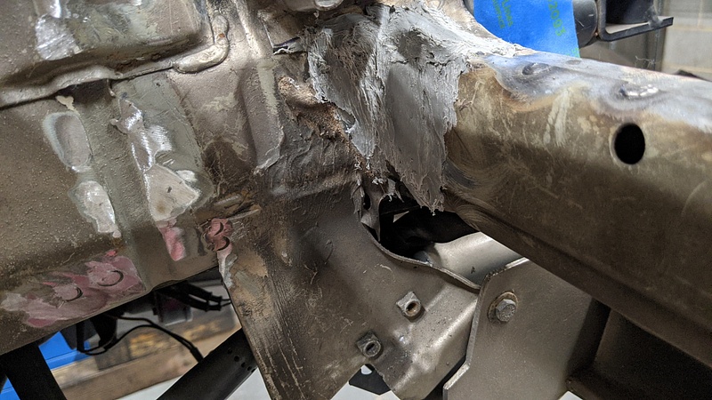
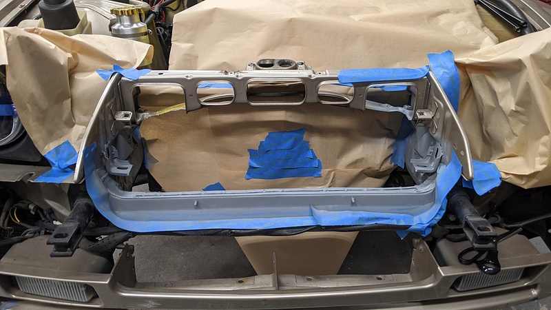
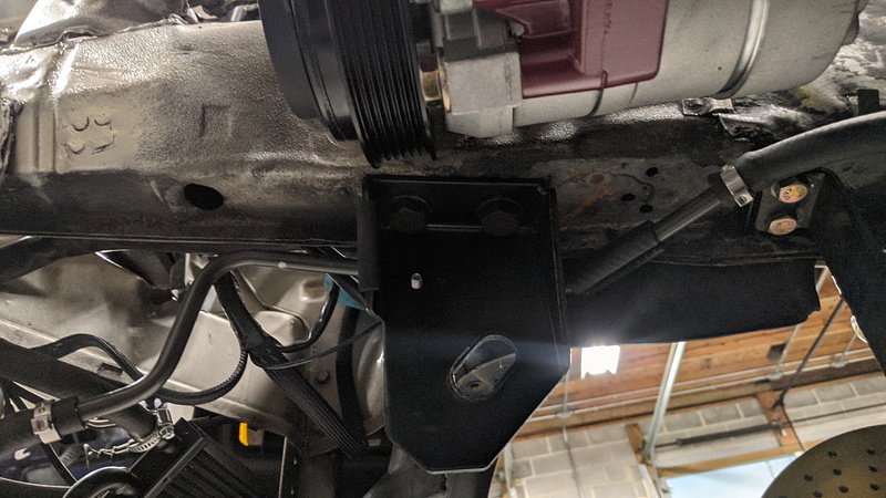
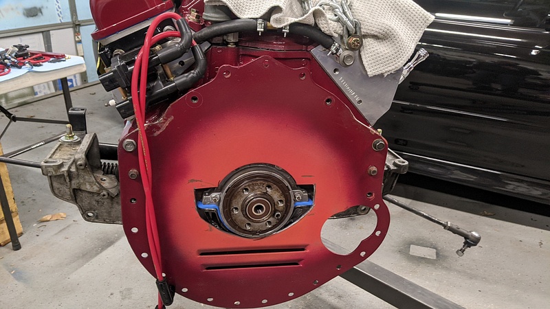
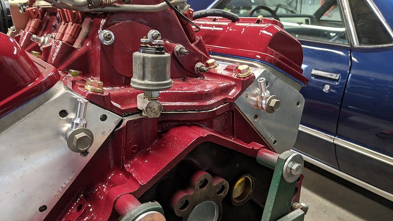
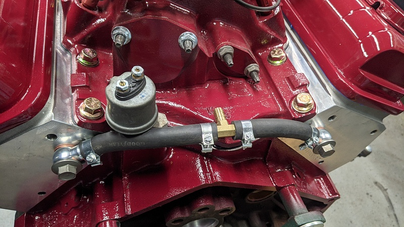
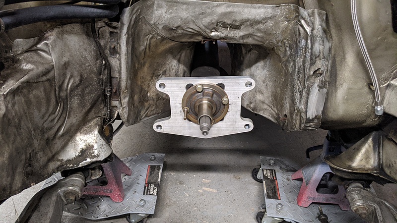
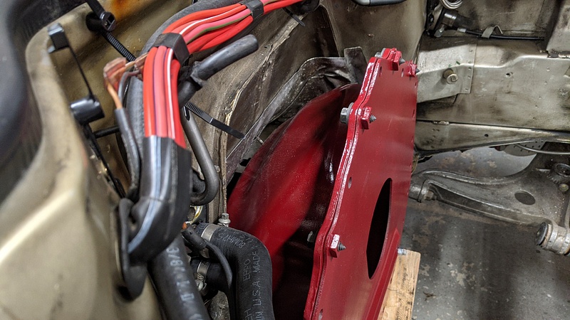
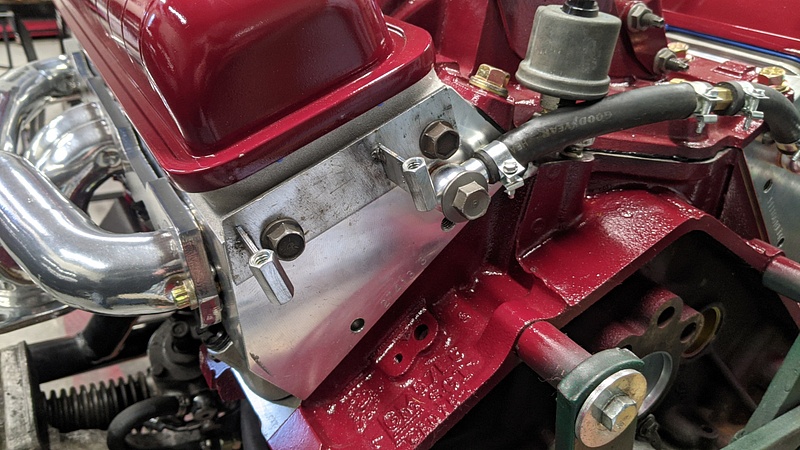
The next thing I needed to do was set the depth of the input shaft so that it would actually engage minor things like the clutch and pilot bearing. Since I already had the number from when I mocked up the bellhousing on the torque tube, I just needed to get the motor off the stand and mock up the bellhousing on it. That's when I discovered that the engine plate did not fit. This little shield-esque shape in front of the input shaft was not going to cut it:
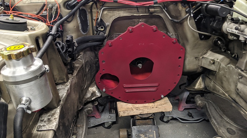
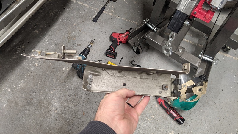
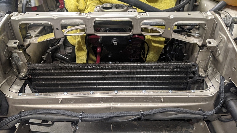
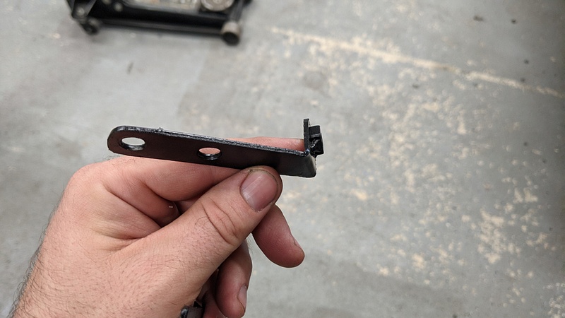
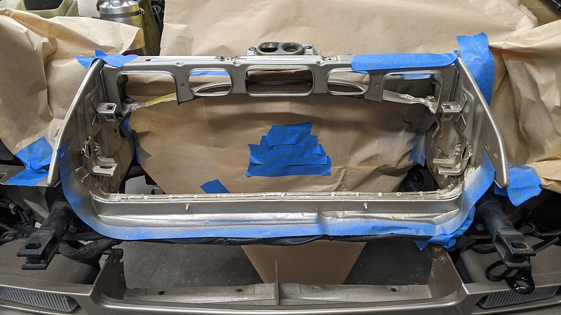
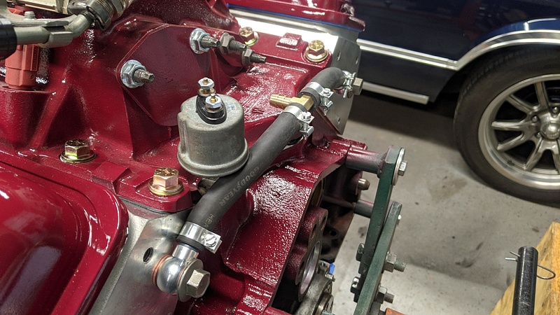
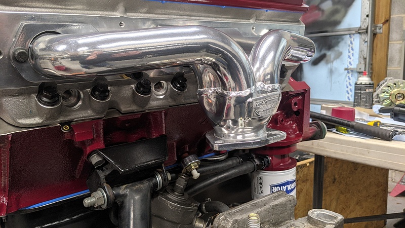
So, out came the angle grinder. And two of those extra bolt ears fell victim, as well. They weren't playing well with my lovely coil pack placement. This was the end result:
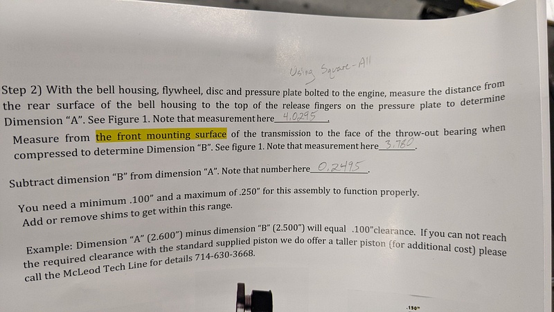
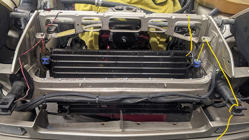
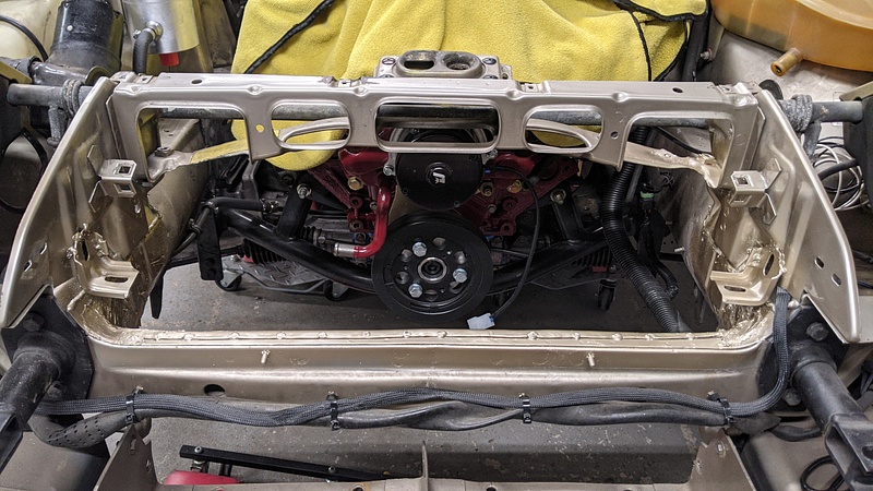
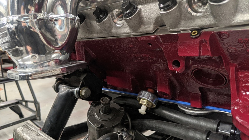
With that out of the way, I could finally measure from the end of the bellhousing to the face of the pilot bearing:
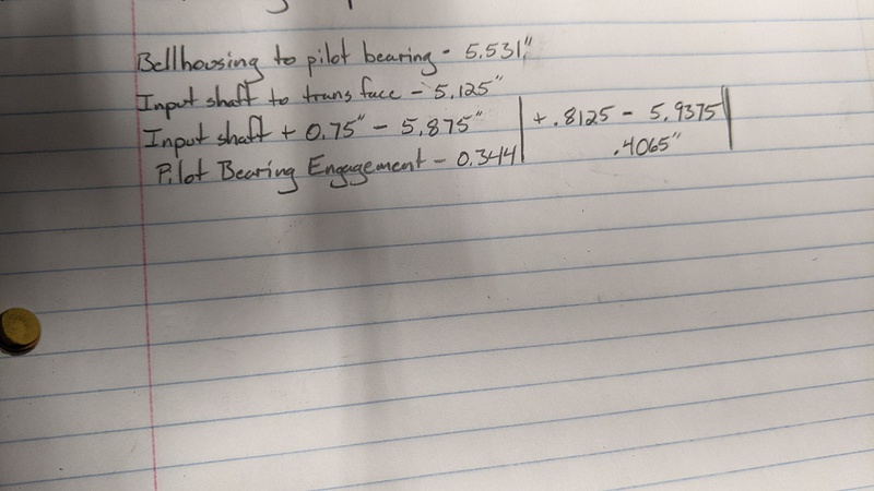
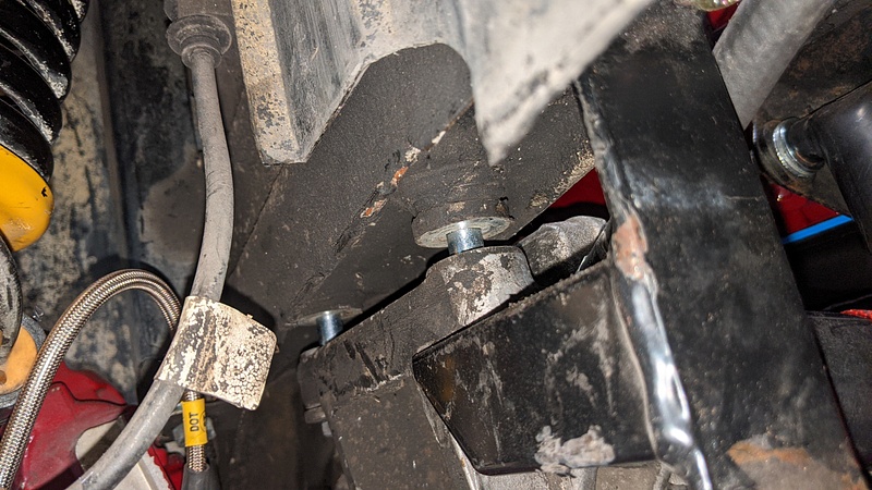
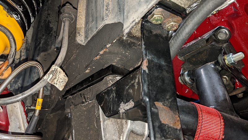
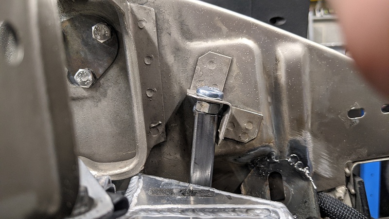
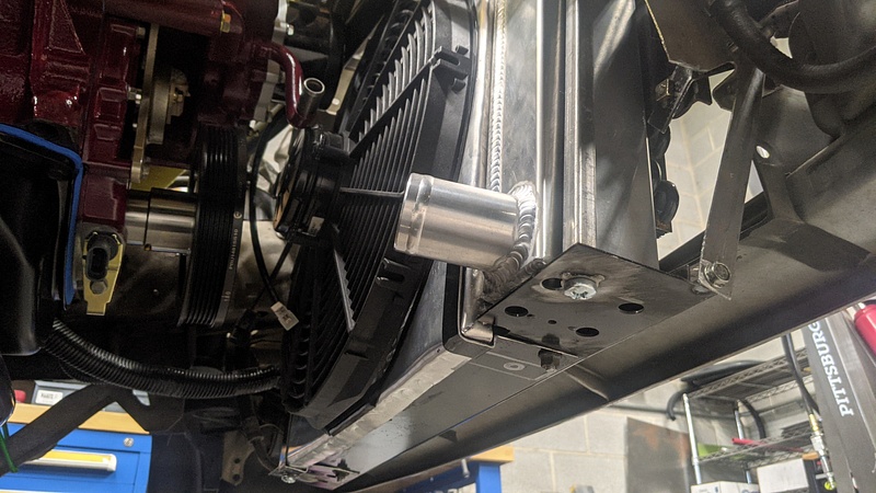
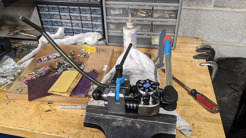
I wound up using a pulley puller to push the shaft in the torque tube forward by 13/16" of an inch. This will allow for the shaft to have about .4" of engagement with the pilot bearing. The shaft actually moves in the torque tube rather easily, and pressed forward by me spinning the puller by hand. I had a friend stand at the engine bay and watch the tube to make sure I didn't go too far forward.
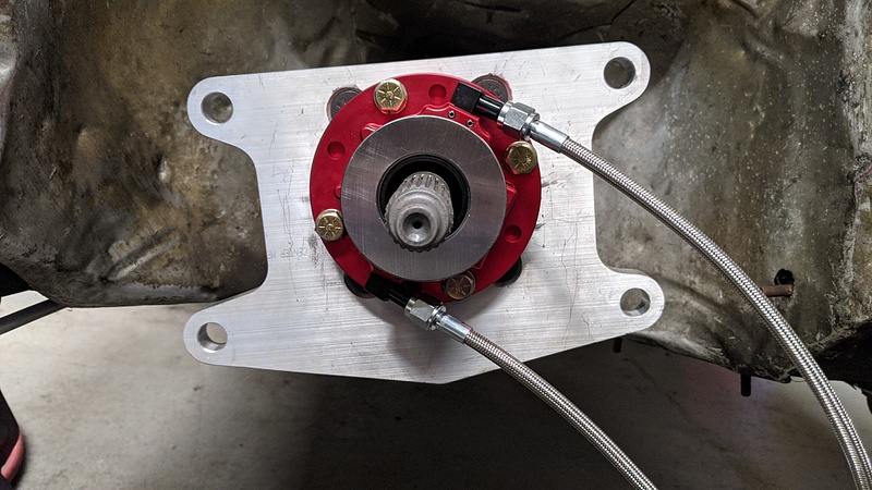
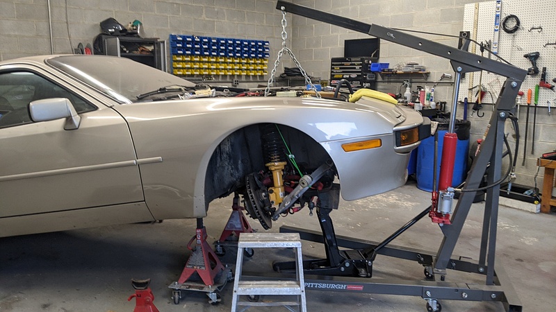
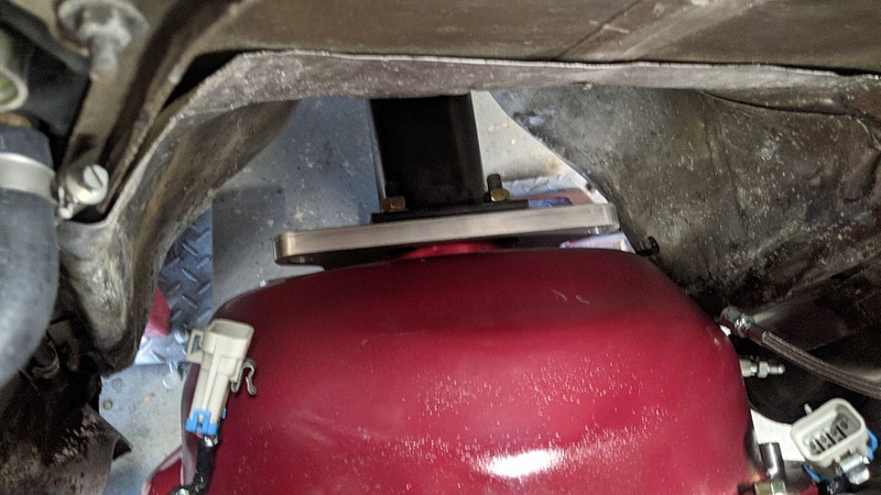
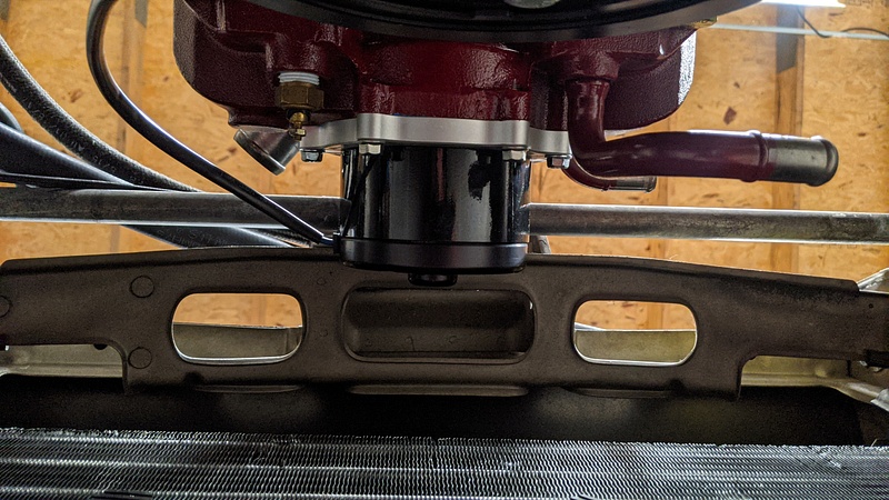
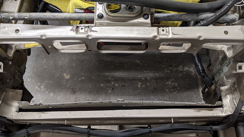
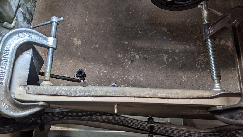
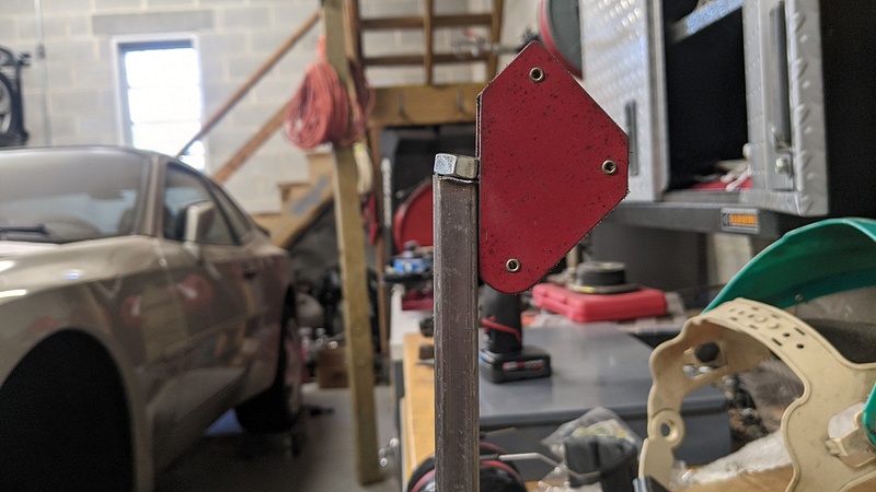
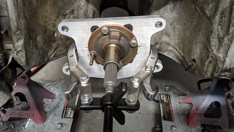
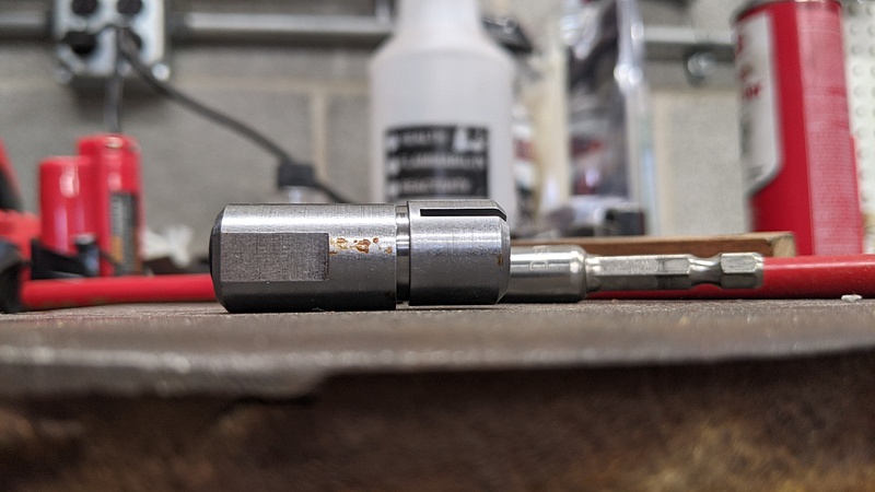
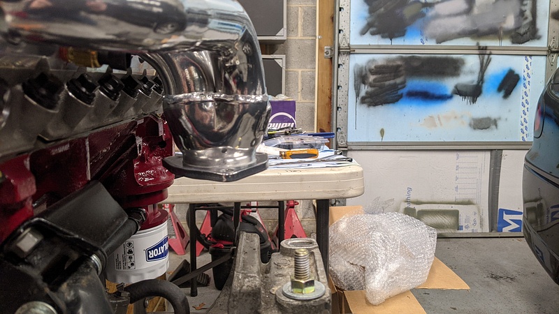
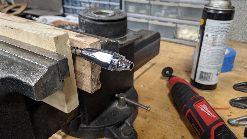
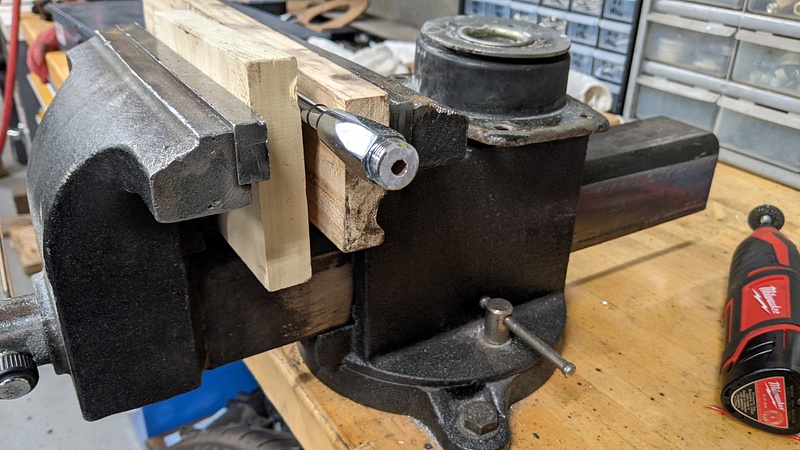
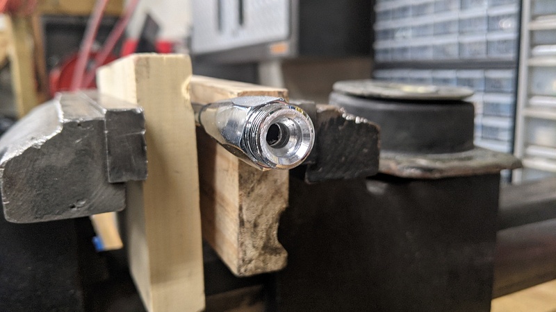
Here is a picture of the puller setup on the front of the torque tube...because my friend wasn't watching closely enough:
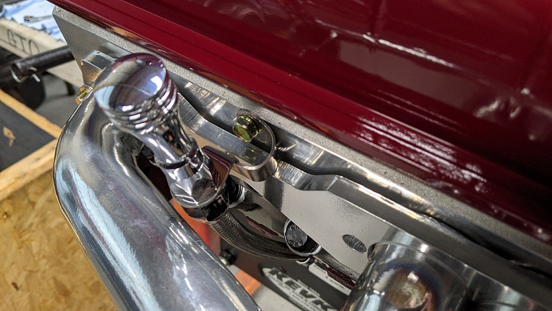
Next up was verifying the bellhousing alignment. I don't think this is as critical with a torque tube, but I wanted to verify it. There are more numbers than there should be, but the first go around of measuring was botched after I realized the bellhousing was not sitting fully on the dowels and I had to tap them further out for full engagement.
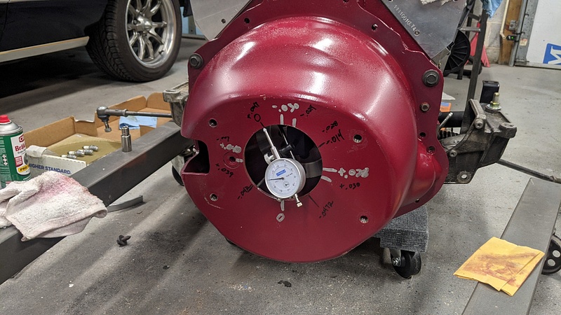
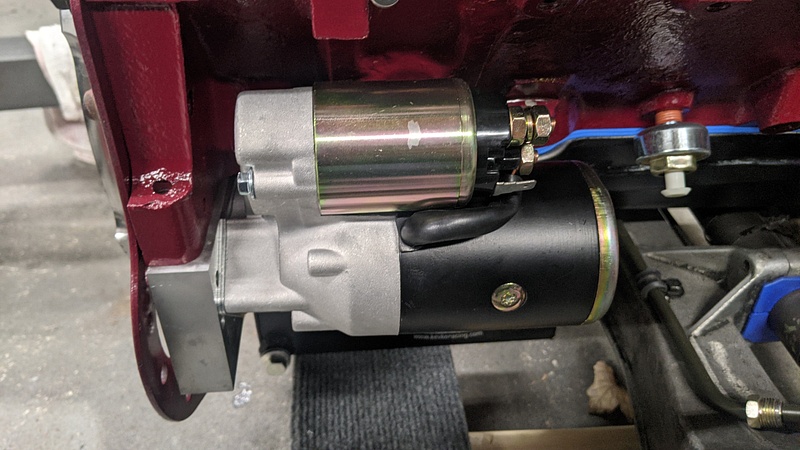
Sure enough, I needed .021" offset dowels to get things square. I ordered a set from RobbMcPerformance. While I played the waiting game on the dowels, I decided to get the starter fitted up. It is a unit from Speedway Motors. It isn't infinitely clockable like the Powermaster I have on the GTO, but this motor isn't running long tubes, so it should suffice. I wound up needed to shim the starter out to get adequate clearance from the flywheel.
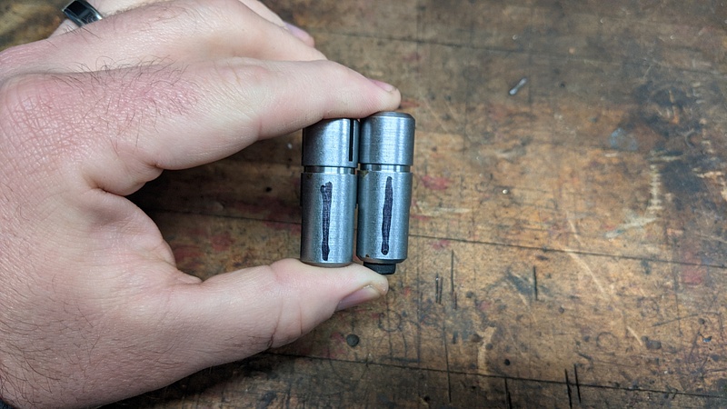
Once the dowels arrived, I put them on a flat surface and marked the offset side:
I probably should have verified that the offset was truly .021" before installing the dowels. When I fit everything back up, I was still getting .008" of runout, which tells me that I either measured incorrectly and needed a custom .028" offset dowel, or I was accidentally sent a .014" offset dowel. Either way, I'm leaving it as I think it will be fine with the torque tube.
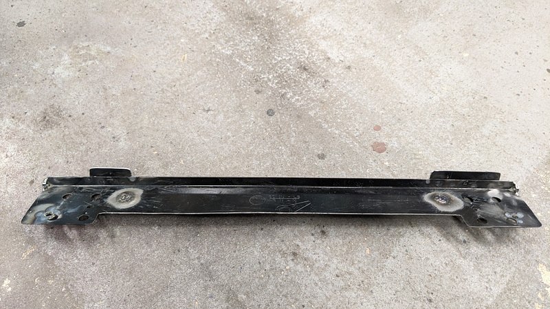
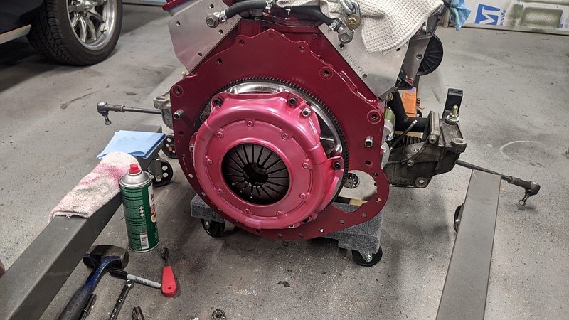
My clutch setup is a bit of a hodgepodge. I wound up using a billet steel flywheel from Spec (SC35S).
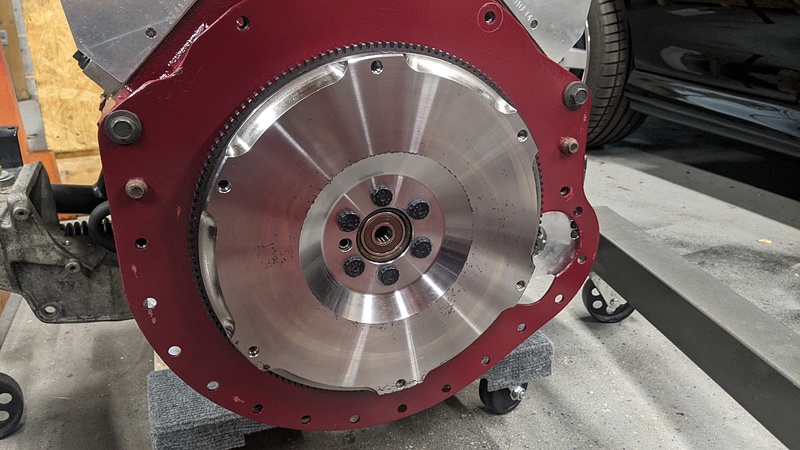
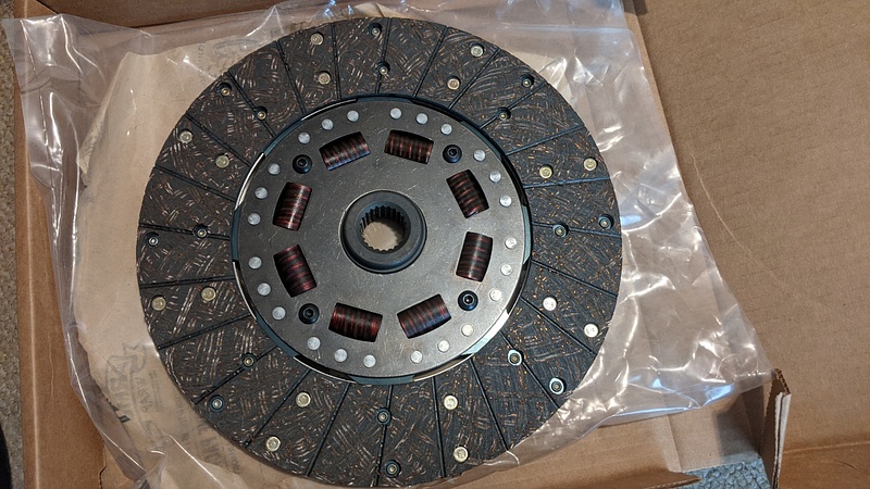
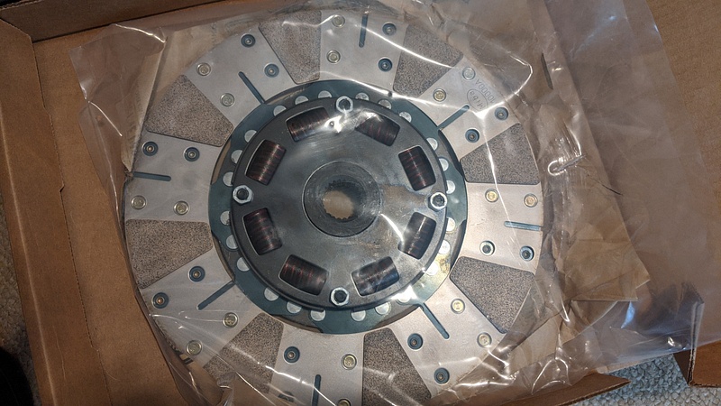
The clutch disc is a Ram 973. This is a 10.5" clutch that is splined for early Mopar cars. The 1" x 23 spline fits perfectly on the 944 torque tube. This disc is their Powergrip series with a full face organic on the flywheel side and a raid metallic puck on the pressure plate side. I had a similar hybrid disc in my GTO many years ago and it was a great unit.
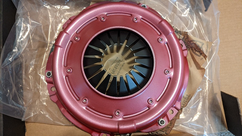
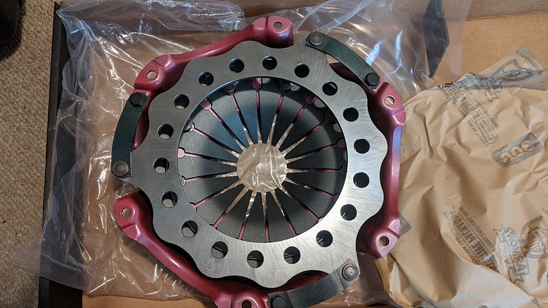
The pressure plate is a Ram 851. It is a 10.5" lightweight pressure plate.
Altogether, the flywheel weight is 18.66lbs, the pressure plate is 11.8lbs, and the clutch disc is 5lbs, totaling 35.46lbs for the entire assembly. I could have saved an additional 8lbs going with Spec's aluminum flywheel, but I think this weight will strike a nice balance for driving it on the street. I can always swap to a lighter flywheel later on if I feel so inclined. Easier said than done, but it is still doable.
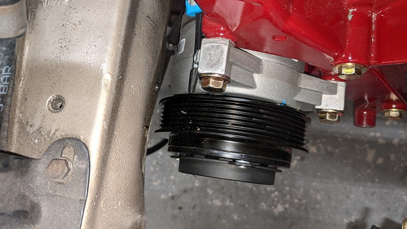
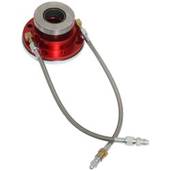
This brings me to the latest hangup. Back when my dad was planning on using the Muncie in his Impala, I had purchased a Quarter Master hydraulic release bearing for the clutch. Since he upgraded to a TKO500 and wound up not needing that bearing, I had planned on using it for my 944 since my adapter plate uses a Muncie bearing retainer. Unfortunately, after measuring for clutch gap, I found that the bearing sticks out about .028" beyond the clutch fingers, which isn't good. I initially looked around for a bearing retainer that was shallower and would allow the bearing to sit closer to the adapter, but that doesn't seem to exist. After looking around, I had two choices, and both required the purchase of a new bearing kit: Howe 82876, which is for a T5 and has a compressed height of 1.52" instead of the Quarter Master's 1.69", or McLeod 1300-1, which is for a Muncie "when the distance from the rear surface of the bell housing to the top of the release fingers on the pressure plate is 2.31 in. to 2.50 in," and it replaces the entire bearing retainer. The price of the Howe is much more appealing, but after reading reviews, it appears that the Howe units are prone to leaking in short time, and I wasn't really crazy that the unit didn't have a separate arm for the bearing's body to ride on the stud.
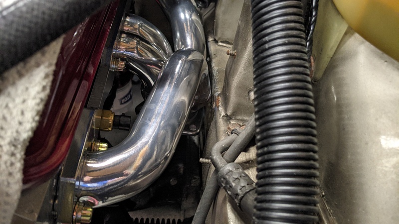
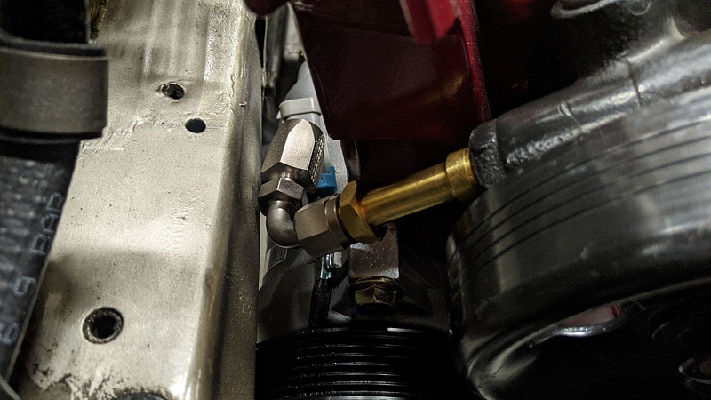
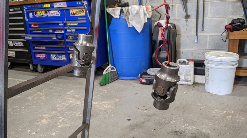
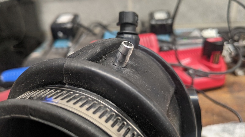
You can see the arm I'm referring to on the Quarter Master:

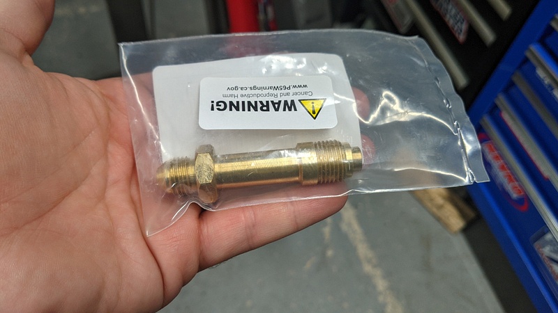
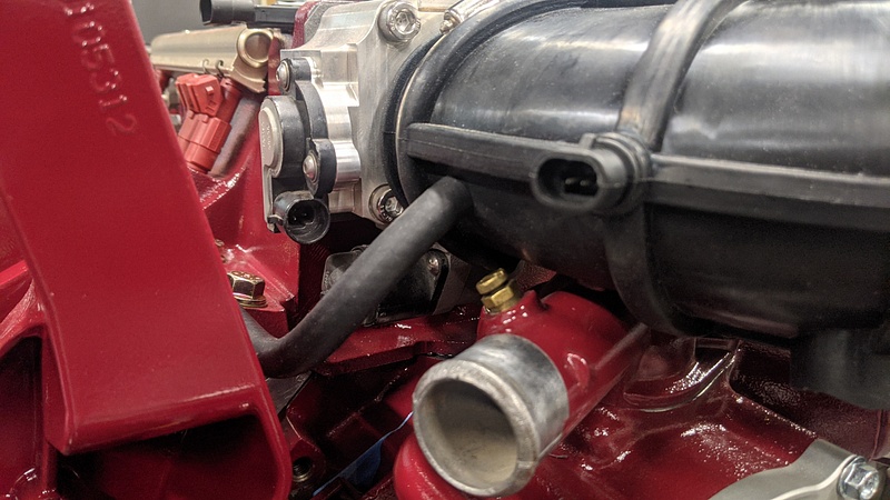
The Howe unit just places the stud between the fittings themselves:

So, I ordered the McLeod bearing. Hopefully, it will arrive in a week and I can get the clutch gap set and finally move towards getting the engine into the car.
and I vote for a 5x8 oval in the stock location with a tip mounted right to it. Muffler is slightly visible, will look a tad more sleeper like that.
 every time I check in here. Also, interesting on the "Fram Racing Filter." I thought Fram was garbage.
 engine porn.
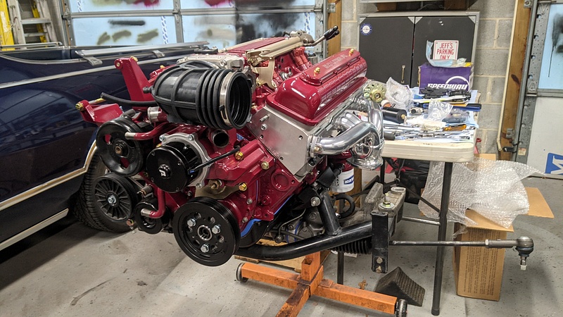
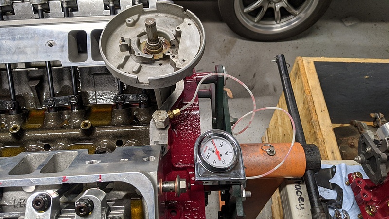
 worthy.
 people.

 like every single thing is beyond my skill level.